Functional description – Akg DMM8 ULD Digital Automatic Microphone Mixer with LAN and DANTE Interface User Manual
Page 90
fUnctionAL Description
DMM8 MANUAL
90
7
Functional description
7.1
Control concept
The device is controlled using the total of 9 rotary knobs on the front
panel. These are labeled
IN 1
to
IN 6
,
SYSTEM CONTROL
,
OUT
and
HEADPHONE
.
The rotary knobs on the inputs are each surrounded by an LED ring with
15 yellow LEDs, one green LED and one red LED. The
SYSTEM CONTROL
rotary knobs and the rotary knobs on the outputs are surrounded by 15
yellow LEDs. The control display under the outputs has 6 green, one yellow
and one red LED.
The LED rings help to visualize the rotary knob setting or display signal
levels.
7.2
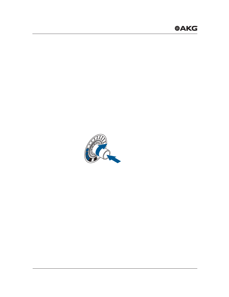
Operation of the rotary knobs
Figure 16:
Rotary knob
•
Turn
the rotary knob
clockwise or
counter-clockwise to make
changes to inputs and outputs and function settings. These chang-
es are shown on the LED ring around the rotary knob. The starting
point and the increments on the LED ring will vary according to the
function.
•
Briefly pressing
the
SYSTEM CONTROL
rotary knob switches
the display on the LED rings to VU meter, the display of the actual
audio level present.
When the VU meter mode is activated, the
LEVEL
LED flash
-
es on the
SYSTEM CONTROL
rotary knob. Pressing the
SYSTEM CONTROL
rotary knob again deactivates the VU meter
mode.
Rotary knob
8
ON
PEAK
9 10 11
12
13
14
15
7
6
5
4
3
2
1
IN 2