Description – Akg DMM8 ULD Digital Automatic Microphone Mixer with LAN and DANTE Interface User Manual
Page 80
Description
DMM8 MANUAL
80
No. Description
25
Mains switch
26
Mains connection
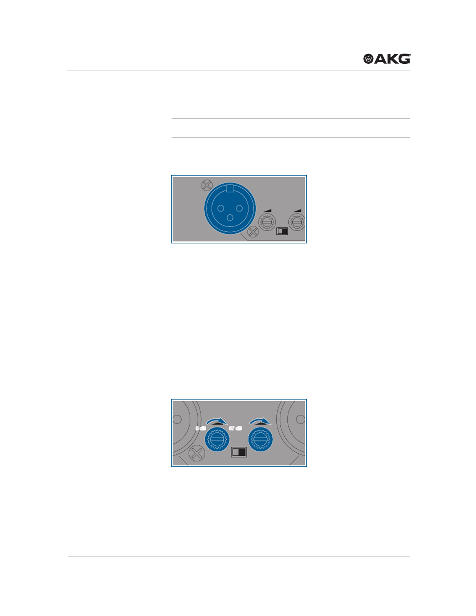
5.4.1 Inputs
Figure 3: Input
The 6 balanced input channels (1, 5, 6, 10, 11, 15) can be accessed via
3-pin
Phoenix
sockets. These are labeled
IN 1
to
IN 6
. The input levels can
be controlled with the rotary knobs
IN 1
to
IN 6
on the front panel.
The assignment is labeled via socket IN 3 with:
•
Pin 1 = _|_
•
Pin 2 = a
•
Pin 3 = b
A switch for the phantom power and a gain control for every channel is
located between two
XLR
sockets.
5.4.2 Gain control
Figure 4: Gain controller
Input channels
IN 1
IN 2
Off
PHANT. PWR
On
Gain controller
IN 1
IN 2
Off
PHANT. PWR
On
0 dB
0 dB
57 dB
57 dB
This manual is related to the following products: