Description – Akg DMM8 ULD Digital Automatic Microphone Mixer with LAN and DANTE Interface User Manual
Page 81
Description
DMM8 MANUAL
81
The associated gain control is located next to every input channel
(2, 4, 7, 9, 12, 14) to set the input level. The gain controls are equipped with
integrated switch for the left side stop.
The input level is set at 0 dB when the left end stop is reached By turning
the control clockwise the gain can be increased by max. 57 dB.
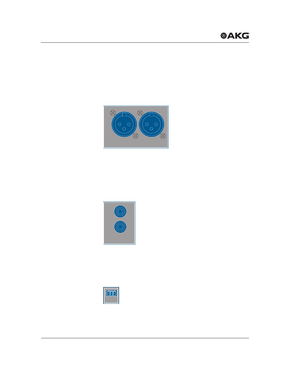
5.4.3 Stereo master output
Figure 5: Stereo master output
The device has one balanced master output (16, 17). It is accessible via two
3-pin
XLR
sockets. The outputs are labeled
OUT L
and
OUT R
.
The
OUT
rotary knob on the front can be used to make settings on the out-
put level of the stereo output.
5.4.4 Stereo record output
Figure 6: Stereo record output
Two RCA jacks, labeled
REC (OUT)
(18) are available for connecting stereo
recording equipment. The allocation of the individual channels to the unbal-
anced stereo recording output can be configured as desired.
5.4.5 Serial control via RS232
Figure 7: Serial control
Stereo output
OUT L
OUT R
Stereo record
output
REC (OUT)
L
R
Serial control
RS232