ATL Telecom OM100 User Manual
Page 27
ATL USER GUIDE
OM100 Optical Multiplexer
51
7.2
CONFIGURATION
7.2.1
Master/Slave configuration
In order for a pair of units to operate correctly, one end must be set as a master, the other end
as a slave. Normally the unit connected to the customer will be configured as a slave.
OM100 Mon 01 Nov 2002 00:40:26
Configuration > Master/Slave Operation
Urgent Alarm:On Non-Urgent Alarm:Off
Master (*)
Slave ( )
Saving changes to this screen will cause unit to reboot
Press Return to Accept or Escape to Cancel
F1 Help F3 Previous Menu F4 Main Menu
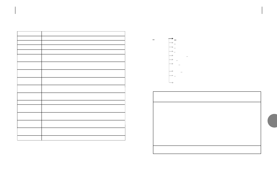
Configuration
Master / Slave
Master / slave configuration.
User Port
Configure each E1 port – enable.
Protection Switching
Configures the protection 1+1 switching.
System
Set date, time and menu timeout.
Subsystem Names
Enter name, description and location of this unit.
Monitoring Mode
Configures monitoring mode.
Software
Allows the downloading of software to the unit
and allows reset to factory default.
Serial Communications
Local terminal set-up – baud rate, parity, handshake.
Reboot
This option allows you to reboot the unit that you
are using, as well as its remote partner.
Front Panel
Allows configuration of Front Panel controls.
7
50
ATL USER GUIDE
OM100 Optical Multiplexer
7.1.3.2
Alarm sources
*Where n = 1..4 and m = 1..2
Definition
Restart activated by power failure.
Restart activated by the software.
AIS detected on user port (applies to each of the 4 ports).
LOS detected on user port (applies to each of the 4 ports).
High bit error rate on user port (applies to each of the 4 ports).
Low bit error rate on user port (applies to each of the 4 ports).
Failed logon attempt.
Error whilst retrieving stored configuration.
Internal
fault
Internal
fault
Sync loss detected on optical port (applies to each optical port).
High bit error rate on optical port (applies to each optical port)
Low bit error rate on optical port (applies to each optical port)
Fault detected on the optical transmitter (applies to each optical port)
APS has switched to the backup link
Loopback, or test mode active
Fault description
Cold Boot
Warm Boot
User Port n* AIS
User Port n* LOS
User Port n*
BER > 1E3
User Port n
BER > 1E6
Security –
password rejected
H/W – Configuration
Memory Fail
H/W – FPGA
Configuration Fail
Failed to program
(Fault:%n)
Optical Port LOS
Optical Port m*
BER > 1E-3
Optical Port m*
BER > 1E-6
Optical Port m*
Laser Fault
Optical Port –
Backup Link Active
Test active