ATL Telecom OM100 User Manual
Page 13
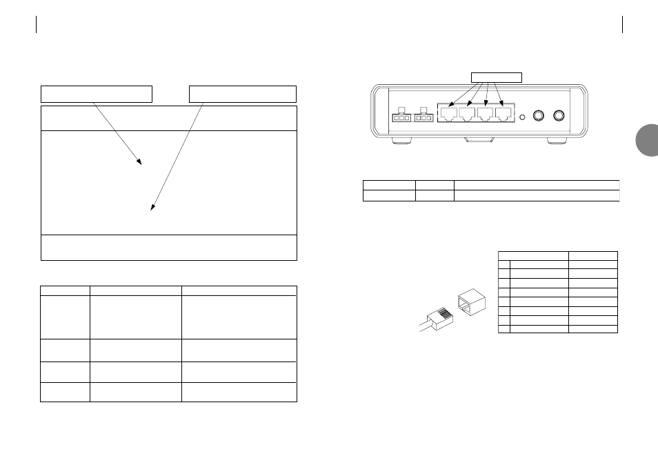
3.6
CONNECTING TO THE E1 USER PORTS
FIGURE 3.5 USER PORT LOCATIONS
Each of the four user ports has the same group of common components:
Note: The 120
Ω connection is also known as balanced G.703.
3.6.1
Pin assignments
The 8 way RJ45 connectors present a balanced
120
Ω Interface conforming to the G.703 standard.
Cables are normally wired ‘crossed-over’.
The transmit pair, on pins 1 & 2,
connect to the receive pair of
the terminal equipment
(pins 4 & 5).
8-way RJ45 connector
Signal direction
1 Transmit a
out
2 Transmit b
out
3 Transmit ground
–
4 Receive a
in
5 Receive b
in
6 Receive ground
–
7 not used
–
8 not used
–
Component
RJ45 connector
Marking
Function
Transmit and receive G.703 data, with 120
Ω impedance.
1~ 4
four EI user ports
3
ATL USER GUIDE
OM100 Optical Multiplexer
23
22
ATL USER GUIDE
OM100 Optical Multiplexer
3.5.7
Troubleshooting - Optical Transmission
Use the Performance > Optical Transmission Line screen to quickly identify faults.
Alarm
LOS detected
BER>10E-6
BER>10E-3
Lazer Fault
Problem
Incoming signal is not present
(LOS - Loss Of Signal)
Small number of bit errors on the
optical port
High number of bit errors on
optical port
Optical transmission power out
of range
Cause
• Optical cable is broken
• Optical cable is faulty
• Remote partner unit not powered on
• Dirt on optical connectors
• Dirt on optical counters
• Optical cable too long
• Dirt on optical connectors
• Optical cable too long
• Hardware fault
OM100 Mon 01 Nov 2002 00:53:36
Performance > Optical
Urgent Alarm:Off Non-Urgent Alarm:On
Subsystem: LT
Port: Main Link Backup Link Active [ ]
Laser Fault [ ] BER > 10E-3 [ ]
LOS Detected [ ] BER > 10E-6 [ ]
Line Code Violations 0 Trip Counter 0
Available Seconds 491 Trip Counter 491
Unavailable Seconds 0 Trip Counter 0
Severely Errored Seconds 0 Trip Counter 0
Errored Seconds 0 Trip Counter 0
Error Free Seconds 491 Trip Counter 491
Press Escape to Exit
F1 Help F3 Previous Menu F4 Main Menu F5 Previous Link F6 Next Link
F7 Previous Subsystem F8 Next Subsystem F9 Reset Trips
F10 Reset System Counters
LOS indicates that no signal is present
Counters start when unit is powered.