ATL Telecom OM100 User Manual
Page 17
The single colour LED indicators are interpreted as follows:
Master (Green)
When lit, this LED indicates that the unit has been configured to operate as a 'master'. The
default setting is for the unit to be a 'slave', in which case the LED will be turned off.
Test (Red)
This will be illuminated whenever a loop test is active in the system. i.e. The LED will
illuminate no matter which end of the link the test is applied.
ATL USER GUIDE
OM100 Optical Multiplexer
31
30
ATL USER GUIDE
OM100 Optical Multiplexer
3.7.1.4
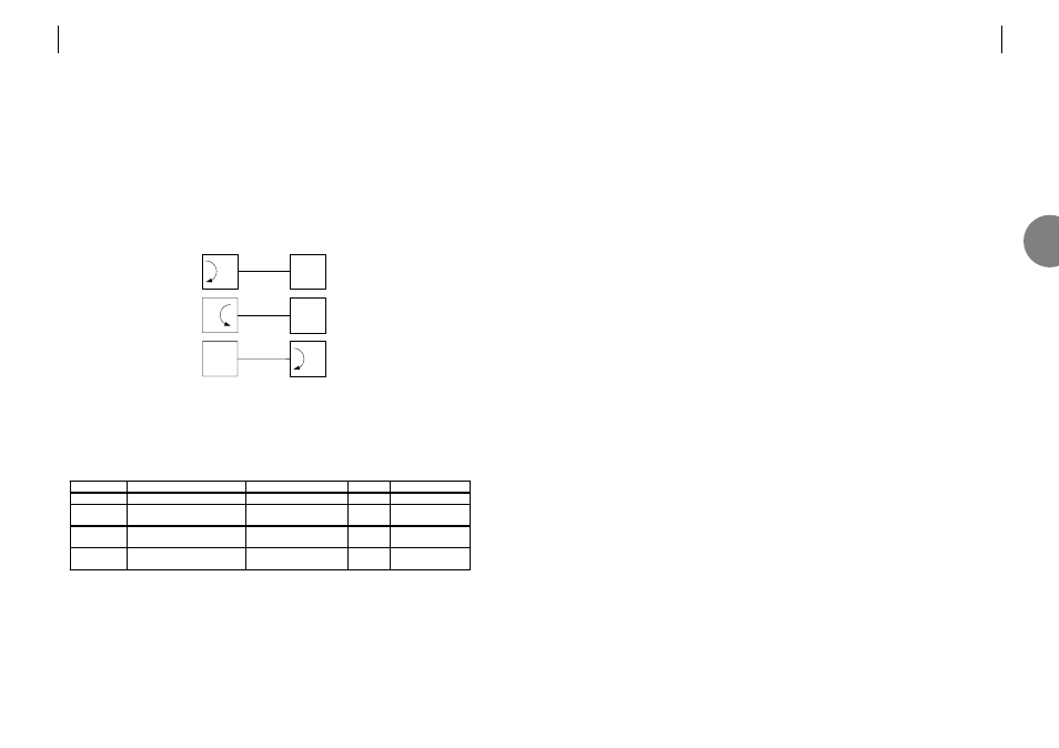
Setting Loops
The following test loops may be set using the front panel buttons.
o Local Loop
o Loop back
o Remote Loop
Note. These buttons may be disabled from the 'Configuration > Front Panel' menu.
3.7.2
Indicators
There are seven tri-colour LEDs that provide status information. These are interpreted as
follows:
*The status LED flashes Green when the unit is in programming mode.
+only active on OM100 1+1 SF SM units.
LED
Red. Urgent
Amber.
Non-Urgent
Green
Off
Status*
System Alarm
System Alarm
OK
Power OFF
Optical 1
Optical Alarm
e.g. LOS, High BER
Optical Alarm
e.g. Low BER
OK N/A
Optical 2
+
Optical Alarm
e.g. LOS, High BER
Optical Alarm
e.g. Low BER
OK N/A
Ch.1. .4
User Port Alarm
e.g. LOS, AIS, High BER
User Port Alarm
e.g. Low BER
OK
No input signal
at user port
Local Loop
Loop back
Remote Loop
Local Unit
Remote Unit
3