Brother HL-1060 User Manual
Page 58
III-19
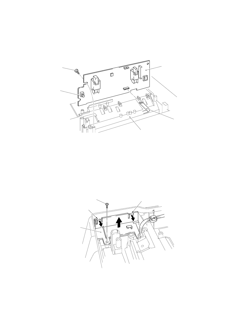
3.14
High-voltage Power Supply PCB ASSY
(1)
Remove the screw securing the high-voltage power supply PCB ASSY.
(2)
Disconnect the HV flat cable from the PCB.
Fig. 3.30
Note:
When reassembling, the flat side of the density dial shaft must be aligned with the
flat side of the density dial plastic adjustment cover.
3.15
Fan Motor ASSY
(1)
Remove the screw securing the fan motor ASSY.
(2)
Release the two hooks of the fan holder from the main cover.
Fig. 3.31
Screw
Density dial
Main cover
HV flat cable
High-voltage power
supply PCB ASSY
Screw
Fan motor ASSY
Hook
Hook
See also other documents in the category Brother Printers:
- HL-2240 (522 pages)
- HL-2240 (21 pages)
- HL-2240 (150 pages)
- HL-2240 (2 pages)
- HL 5370DW (172 pages)
- HL-2170W (138 pages)
- HL 5370DW (203 pages)
- HL 2270DW (35 pages)
- HL 2270DW (47 pages)
- HL 5370DW (55 pages)
- HL-2170W (52 pages)
- HL-2170W (137 pages)
- PT-1290 (1 page)
- MFC 6890CDW (256 pages)
- DCP-585CW (132 pages)
- DCP-385C (2 pages)
- DCP-383C (7 pages)
- DCP-385C (122 pages)
- Pocket Jet6 PJ-622 (48 pages)
- Pocket Jet6 PJ-622 (32 pages)
- Pocket Jet6 PJ-622 (11 pages)
- Pocket Jet6Plus PJ-623 (76 pages)
- PT-2700 (62 pages)
- PT-2700 (90 pages)
- PT-2700 (180 pages)
- PT-2100 (58 pages)
- PT-2700 (34 pages)
- HL 5450DN (2 pages)
- DCP-8110DN (22 pages)
- HL 5450DN (168 pages)
- HL 5450DN (2 pages)
- DCP-8110DN (13 pages)
- HL 5470DW (34 pages)
- HL-S7000DN (9 pages)
- HL 5470DW (30 pages)
- MFC-J835DW (13 pages)
- DCP-8110DN (36 pages)
- HL 5470DW (177 pages)
- HL 5450DN (120 pages)
- HL-6050DN (138 pages)
- HL-6050D (179 pages)
- HL-6050D (37 pages)
- HL-7050N (17 pages)
- PT-1280 (1 page)
- PT-9800PCN (104 pages)