Brother HL-1060 User Manual
Page 48
III-9
3.7
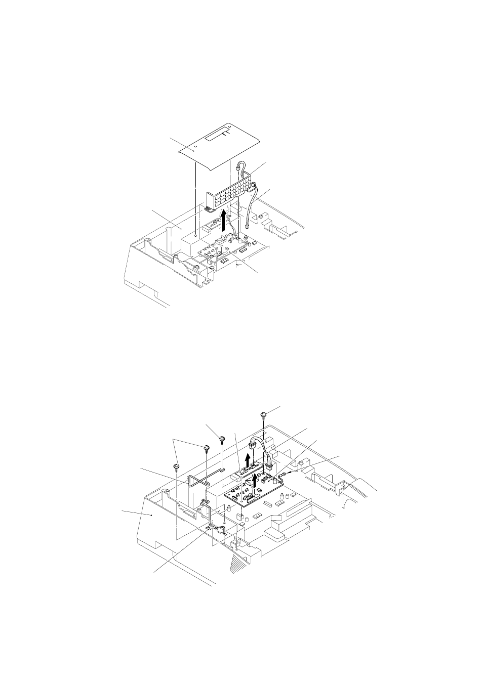
SR PCB / Relay PCB
(1)
Remove the SR protect sheet.
(2)
Disconnect the connector of the SR harness ASSY connecting the SR PCB and
the driver PCB and remove the high-voltage cover.
Fig. 3.12
(3)
Disconnect the connector of the relay harness ASSY connecting the SR PCB and
the relay PCB and remove the two screws on the SR PCB, and remove the SR
PCB.
(4)
Remove the relay PCB.
(5)
Remove the two screws, and remove the electrode SR1, SR2.
Fig. 3.13
SR protect sheet
Taptite, cup B M4x14
High-voltage cover
SR harness ASSY
Relay harness ASSY
Main cover
SR PCB
SR PCB
Ground wire
Relay PCB
Taptite, cup B M4x14
Taptite, cup B
Electrode SR2
Main cover
Electrode SR2
See also other documents in the category Brother Printers:
- HL-2240 (522 pages)
- HL-2240 (21 pages)
- HL-2240 (150 pages)
- HL-2240 (2 pages)
- HL 5370DW (172 pages)
- HL-2170W (138 pages)
- HL 5370DW (203 pages)
- HL 2270DW (35 pages)
- HL 2270DW (47 pages)
- HL 5370DW (55 pages)
- HL-2170W (52 pages)
- HL-2170W (137 pages)
- PT-1290 (1 page)
- MFC 6890CDW (256 pages)
- DCP-585CW (132 pages)
- DCP-385C (2 pages)
- DCP-383C (7 pages)
- DCP-385C (122 pages)
- Pocket Jet6 PJ-622 (48 pages)
- Pocket Jet6 PJ-622 (32 pages)
- Pocket Jet6 PJ-622 (11 pages)
- Pocket Jet6Plus PJ-623 (76 pages)
- PT-2700 (62 pages)
- PT-2700 (90 pages)
- PT-2700 (180 pages)
- PT-2100 (58 pages)
- PT-2700 (34 pages)
- HL 5450DN (2 pages)
- DCP-8110DN (22 pages)
- HL 5450DN (168 pages)
- HL 5450DN (2 pages)
- DCP-8110DN (13 pages)
- HL 5470DW (34 pages)
- HL-S7000DN (9 pages)
- HL 5470DW (30 pages)
- MFC-J835DW (13 pages)
- DCP-8110DN (36 pages)
- HL 5470DW (177 pages)
- HL 5450DN (120 pages)
- HL-6050DN (138 pages)
- HL-6050D (179 pages)
- HL-6050D (37 pages)
- HL-7050N (17 pages)
- PT-1280 (1 page)
- PT-9800PCN (104 pages)