2 vga connector, Figure 4-14: vga connector pinout locations, Table 4-17: vga connector pinouts – IEI Integration SRM_121_150 v1.11 User Manual
Page 63
SRM-121/SRM-150 LCD Monitor
Page 49
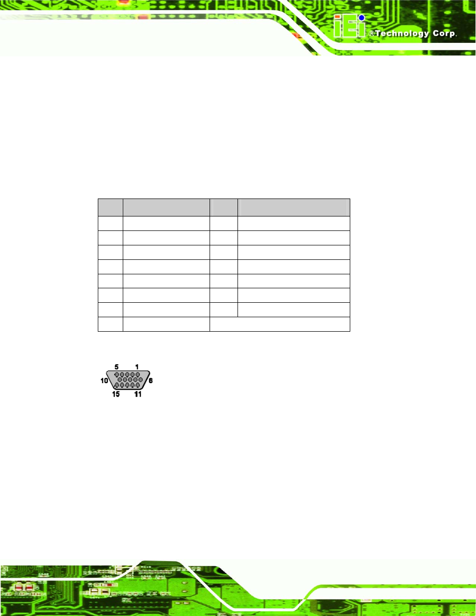
4.4.2 VGA Connector
CN Label:
J5
CN Type:
D-sub 15 female connector
CN Pinouts:
See Table 4-17 and Figure 4-14
CN Location:
Use the standard D-sub 15-pin VGA connector to connect the monitor to a system.
PIN
DESCRIPTION
PIN
DESCRIPTION
1 Red
9 No
Connect
2 Green
10 Ground
3 Blue
11 No
Connect
4 No
Connect
12 DDC
DAT
5 Ground
13 Horizontal
Synchronization
6 Ground
14 Vertical
Synchronization
7 Ground
15 DDC
Clock
8 Ground
Table 4-17: VGA Connector Pinouts
Figure 4-14: VGA Connector Pinout Locations