5 jumper settings, 1 access the jumpers, Umper – IEI Integration PPC-WIDS-51xxA-G41 User Manual
Page 48: Ettings, Table 4-1: jumpers
PPC-51xxA-G41/WIDS-51xA-G41 Panel PC
Page 36
4.5 Jumper Settings
NOTE:
A jumper is a metal bridge that is used to close an electrical circuit. It
consists of two metal pins and a small metal clip (often protected by a
plastic cover that slides over the pins to connect them. To
CLOSE/SHORT a jumper means connecting the pins of the jumper
with the plastic clip and to OPEN a jumper means removing the plastic
clip from a jumper.
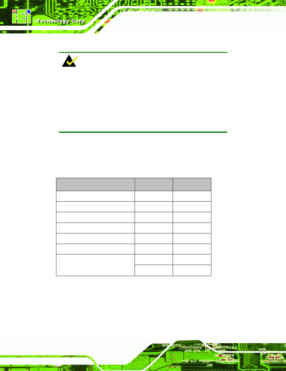
The following jumpers can be found on the motherboard installed in the
PPC-51xxA-G41/WIDS-51xA-G41. Before the PPC-51xxA-G41/WIDS-51xA-G41 is
installed, the jumpers must be set in accordance with the desired configuration. The
jumpers on the PPC-51xxA-G41/WIDS-51xA-G41 motherboard are listed in Table 4-1.
Description
Label
Type
CF Card Setup
JCF1
2-pin header
COM1 Pin 9 setting
J_COM_V1
6-pin header
COM2 Pin 9 setting
J_COM_V2
6-pin header
COM3 Pin 9 setting
J_COM_V3
6-pin header
COM4 Pin 9 setting
J_COM_V4
6-pin header
COM5 Pin 9 setting
J_COM_V5
6-pin header
UART_SEL1 12-pin
header
COM5 RS-232/422/485 Select
UART_SEL2 10-pin
header
Table 4-1: Jumpers
4.5.1 Access the Jumpers
To access the jumpers, remove the back panel. To remove the back panel, please refer to
Section 4.4.