Input internal circuit terminal arrangement, Wiring examples, Ardware – IDEC SX5L Series User Manual
Page 30: Pecifications, Upper terminal block (sx9z-ss11), Lower terminal block (sx9z-ss7)
2: H
ARDWARE
S
PECIFICATIONS
SX5L C
OMMUNICATION
T
ERMINAL
U
SER
’
S
M
ANUAL
2-19
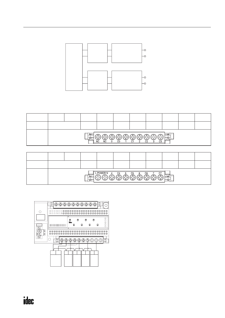
Input Internal Circuit
Terminal Arrangement
•
Upper Terminal Block (SX9Z-SS11)
•
Lower Terminal Block (SX9Z-SS7)
Wiring Examples
Marking
NC
NC
0
C0
1
C1
2
C2
3
C3
Name
No Connection
Output 0
Common
Output 1
Common
Output 2
Common
Output 3
Common
Front View
Marking
POWER
L
POWER
N
4
C4
5
C5
6
C6
7
C7
Name
Power Voltage
Output 4
Common
Output 5
Common
Output 6
Common
Output 7
Common
Front View
Photocoupler
Output 0
Output 1
Remote-control Relay
Control Circuit
Remote-control Relay
Control Circuit
Photocoupler
Internal
Circuit
Common
Common
Blue
Remote-
control
Transformer
White
Blue
Remote-
control
Relay
Red Blue
Remote-
control
Relay
Red Blue
Remote-
control
Relay
Red Blue
Remote-
control
Relay
Red
PWR
SX5L
LON
1
0
4
5
7
6
2
3
RES
SER
ERR
RUN
C7
7
C6
6
C5
5
C4
4
L POWER N
C3
C0
1
C1
2
C2
3
0
NC
NC
OUT
OUT
SERVICE
REQUEST
TYPE: SX5L-SBRR081
Note: Common terminals C0 through C7 and the POWER N
terminal are connected together internally.
Only one remote-control relay can be connected to
each output circuit.