Input internal circuit terminal arrangement, Wiring examples, Ardware – IDEC SX5L Series User Manual
Page 16: Pecifications, Upper terminal block (sx9z-ss10), Lower terminal block (sx9z-ss2), Plus common wiring, Minus common wiring, Sx5l c
2: H
ARDWARE
S
PECIFICATIONS
SX5L C
OMMUNICATION
T
ERMINAL
U
SER
’
S
M
ANUAL
2-5
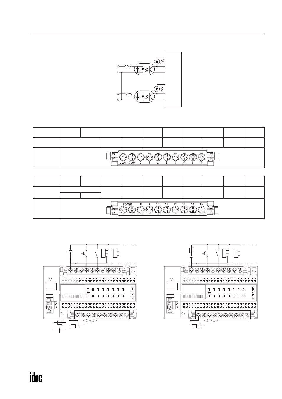
Input Internal Circuit
Terminal Arrangement
•
Upper Terminal Block (SX9Z-SS10)
•
Lower Terminal Block (SX9Z-SS2)
Wiring Examples
Note: The internal circuit and input circuit can be powered by the same power supply.
Two COM terminals are connected together internally.
Marking
COM
COM
0
1
2
3
4
5
6
7
Name
Input Common
Input 0
Input 1
Input 2
Input 3
Input 4
Input 5
Input 6
Input 7
Front View
Marking
POWER
+
POWER
–
8
9
10
11
12
13
14
15
Name
Power Voltage
Input 8
Input 9
Input 10
Input 11
Input 12
Input 13
Input 14
Input 15
24V DC
0V
Front View
Input 0
Common
Input 1
Common
Internal
Circuit
+
–
PWR
SX5L
LON
3
2
1
0
8
9
10
11
15
14
13
12
7
4
5
6
RES
SER
ERR
RUN
15
14
13
12
11
10
9
8
+ POWER –
7
1
2
3
4
5
6
0
COM COM
IN
IN
PNP
–
+
OUT
–
+
+
–
+
–
SERVICE
REQUEST
TYPE: SX5L-SBN16B1
PWR
SX5L
LON
3
2
1
0
8
9
10
11
15
14
13
12
7
4
5
6
RES
SER
ERR
RUN
15
14
13
12
11
10
9
8
+ POWER –
7
1
2
3
4
5
6
0
COM COM
IN
IN
OUT
NPN
+
–
+
–
+
–
+
–
SERVICE
REQUEST
TYPE: SX5L-SBN16B1
+
–
24V DC
Fuse
3-wire
sensor
2-wire
sensor
3-wire
sensor
2-wire
sensor
•
Plus Common Wiring
•
Minus Common Wiring