Input internal circuit terminal arrangement, Wiring examples – IDEC SX5L Series User Manual
Page 24
2: H
ARDWARE
S
PECIFICATIONS
SX5L C
OMMUNICATION
T
ERMINAL
U
SER
’
S
M
ANUAL
2-13
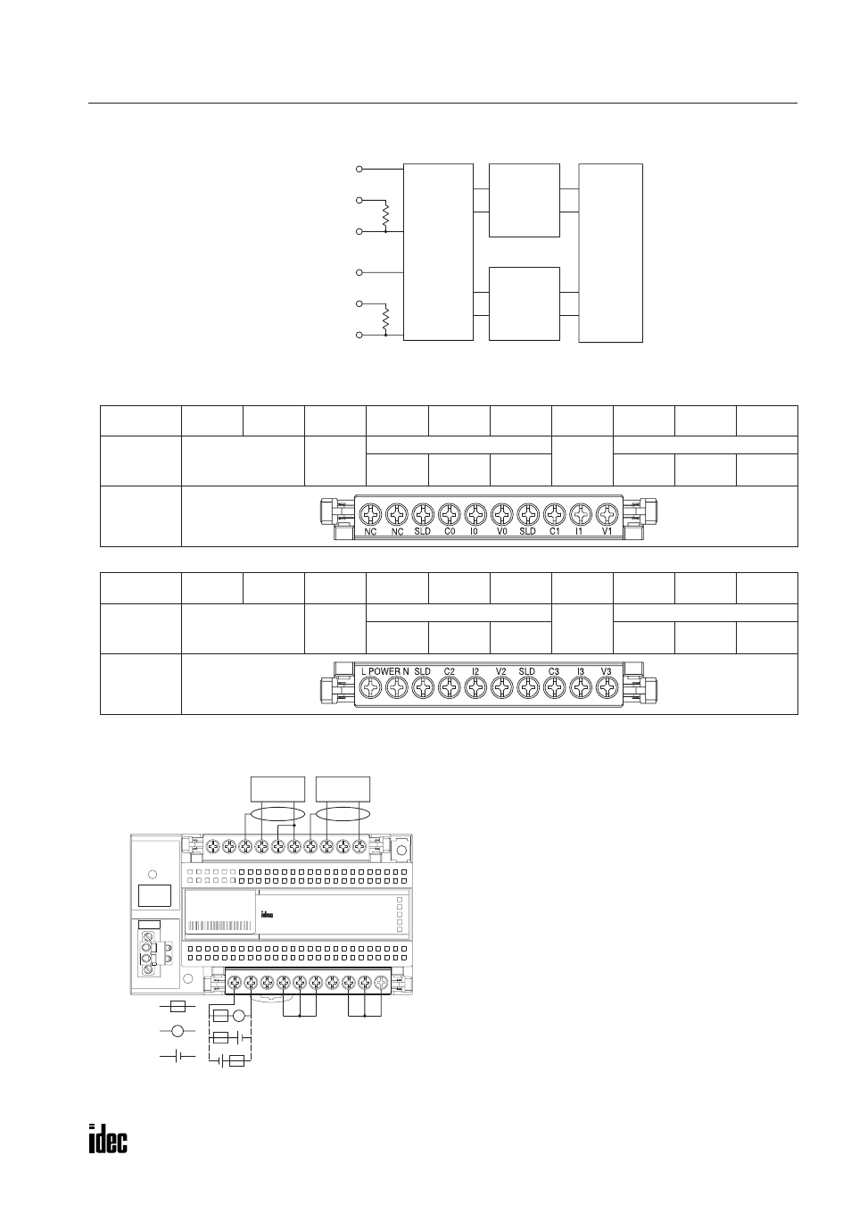
Input Internal Circuit
Terminal Arrangement
•
Upper Terminal Block (SX9Z-SS12)
•
Lower Terminal Block (SX9Z-SS9)
Wiring Examples
Marking
NC
NC
SLD
C0
I0
V0
SLD
C1
I1
V1
Name
No Connection
Shield
Channel 0
Shield
Channel 1
Common
Current
Input
Voltage
Input
Common
Current
Input
Voltage
Input
Front View
Marking
POWER
L
POWER
N
SLD
C2
I2
V2
SLD
C3
I3
V3
Name
Power Voltage
Shield
Channel 2
Shield
Channel 3
Common
Current
Input
Voltage
Input
Common
Current
Input
Voltage
Input
Front View
Channel 0 Voltage Input
Channel 0 Current Input
Channel 0 Common
Channel 1 Voltage Input
Channel 1 Current Input
Channel 1 Common
A/D
Conversion
Circuit
Photocoupler
Internal
Circuit
Isolation
Power
Supply
PWR
SX5L
LON
RES
SER
ERR
RUN
V3
I3
C3
SLD
V2
I2
C2
SLD
L POWER N
V1
C0
I0
V0
SLD
C1
I1
SLD
NC
NC
IN
IN
SERVICE
REQUEST
TYPE: SX5L-SBAN041
Termination on unused terminals
+
–
24V DC
Fuse
+
–
+
–
~
24V AC
~
Analog Current
Output Device
Analog Voltage
Output Device
Note: Connect together the terminals of an unused
channel using an optional jumper BPJ-26B (ring
type) or BPJ-26FB (spade type) or using wires.