Wiring with tank side monitor 4590 – Lightning Audio 7532 User Manual
Page 27
27
7532
Wiring
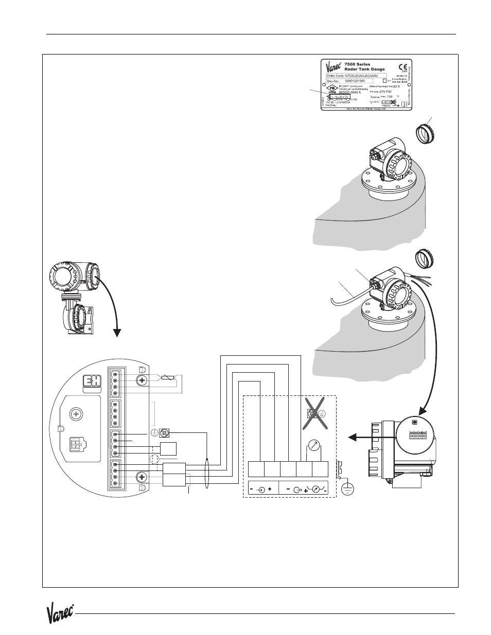
Wiring with Tank Side Monitor 4590
-
1 2 3 4 5
1
3
2
4
5
RTD
NRF 590 i.s. terminal board
i.s. module wiring
HART
sensor
+
-
-
+
16
17
18
19
D+
S+
S-
D-
20
21
22
23
OPT1
OPT2
OPT3
OPT4
24
25
26
27
+
-
+
H
H
-
+
-
+
P
H
-
28
29
30
31
For Micropilot
S-series only!
Internally
interconnected
as one HART
fieldbus loop
2
1
4
3
1 2 3 4
2
4
3
plant
ground
Before connection please note the following:
The power supply must be identical to the data on the
nameplate (1).
Switch off power supply before connecting up the device.
Connect Equipotential bonding to transmitter ground terminal
before connecting up the device.
Tighten the locking screw:
It forms the connection between the antenna and the housing
ground potential.
●
●
●
●
When you use the measuring system in hazardous areas, make sure you comply with
national standards and the specifications in the safety instructions (XA’s).
Make sure you use the specified cable gland.
Caution!
"
Connect up the 7500 RTG as follows:
Before unscrew housing cover (2) at seperate connection room
turn off the power supply!
Insert cable through gland (3).
Use screened, twisted wire pair.
Make connection (see pin assignment).
Tighten cable gland (4).
Screw off housing cover (2).
Switch on power supply.
●
●
●
●
●
grounding not on
7500 RTG
grounding single sided
on Tank Side Monitor
4590 TSM
intrinsicaly safe
terminal board
Tank Side Monitor
4590 TSM
only for
7500 RTG
The 7500 RTG is - possibly in combination with other devices - connected to a Tank
Side Monitor in a hazardous area. In this case, it is recommended that you ground
the cable screen centrally at the Tank Side Monitor and connect all devices to the
same potential matching line (PML). If, for functional reasons, a capacitive coupling is
required between local earth and screen (multiple grounding), ceramic condensers
with a dielectric strength of min. 1500 V
eff
must be used, whereby the total capacitance
of 10 nF must not be exceeded. Notes on grounding interconnected intrinsically safe
devices are provided by the FISCO model
1
75
xx_w
iri
ng
_w
_T
SM.