Lightning Audio 7532 User Manual
Page 26
Wiring
Radar Tank Gauge
26
Installation and Operations Manual
5
-
-
1 2 3 4
1 2 3 4 5
1
3
2
4
5
2
4
3
1
plant
ground
power:
24 VDC
(16…30 V)
signal:
24 VDC
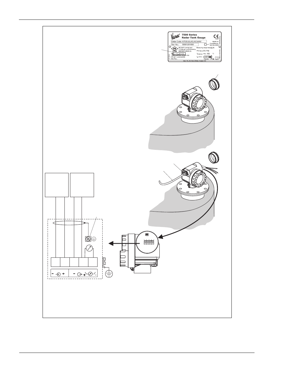
Connect up the 7500 RTG as follows:
Before unscrew housing cover (2) at seperate connection room
turn off the power supply!
Insert cable through gland (3).
Use screened, twisted wire pair.
Only ground screening of the line (5) on sensor side.
Make connection (see pin assignment).
Tighten cable gland (4).
Screw off housing cover (2).
Switch on power supply.
●
●
●
●
●
Before connection please note the following:
The power supply must be identical to the data on the
nameplate (1).
Switch off power supply before connecting up the device.
Connect Equipotential bonding to transmitter ground terminal
before connecting up the device.
Tighten the locking screw:
It forms the connection between the antenna and the housing
ground potential.
●
●
●
●
When you use the measuring system in hazardous areas, make sure you comply with
national standards and the specifications in the safety instructions (XA’s).
Make sure you use the specified cable gland.
Caution!
"
A 7500 RTG situated in a hazardous area is connected as a
single
device
to a power supply unit and transmitter situated outside of
the hazardous area. In this case, it is recommended that the screen
be connected directly to the 7500 RTG at the housing's earth,
whereby the 7500 RTG and the power supply unit are connected to
the same potential matching line (PML).
75
xx_
w
irin
g.e
ps