C. vent components diagrams (continued) – Heat & Glo Fireplace 2197-980 User Manual
Page 65
65
Heat & Glo • SOHO-N-AUB • 2197-980 Rev. G • 2/13
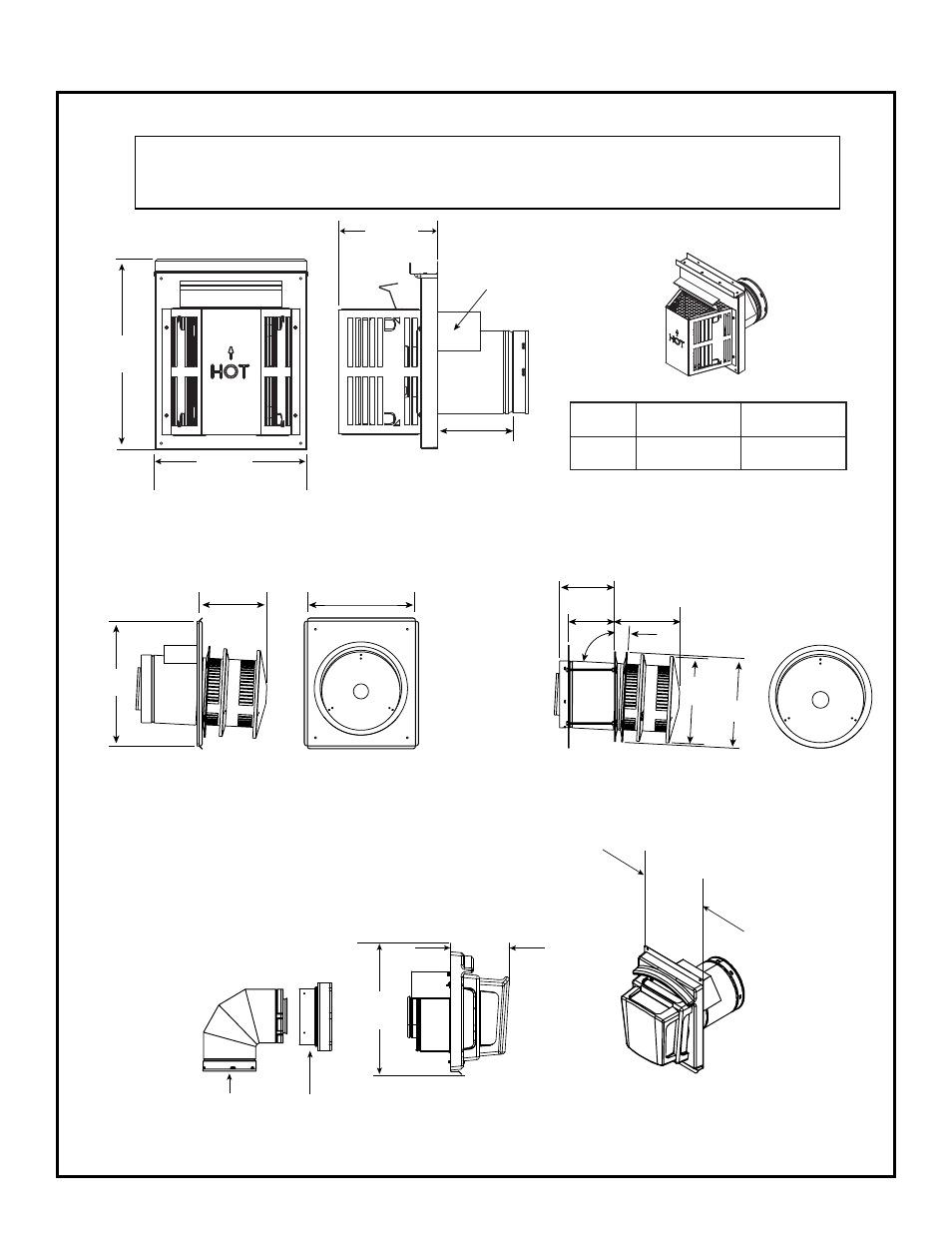
SLP-HRC-SS
SLP-HRC-ZC-SS
HORIZONTAL TERMINATION CAP
C. Vent Components Diagrams (continued)
Figure 16.4 SLP Series Vent Components
SLP90
SL-2DVP
DVP-FBHT
DVP-FBHT
7 in.
(178 mm)
15-1/2 in.
(394 mm)
12 in.
(305 mm)
SLP-TRAP
Horizontal Termination Cap
15 in.
(384 mm)
Note: Heat shields MUST overlap by a minimum of 1-1/2 in. (38 mm). The heat shield is designed to be
used on a wall 4 in. (102 mm) to 7-1/4 in. (184 mm) thick. If wall thickness is less than 4 in. (102 mm) the
existing heat shields must be field trimmed. If wall thickness is greater than 7-1/4 (184 mm) a DVP-
HSM-B will be required.
Heat
Shield
Term Cap
Minimum
Effective Length
Maximum
Effective Length
Trap
(133 mm)
(235 mm)
8 in.
(203 mm)
12 in.
(305 mm)
Max
Effective
Length
5-1/4 in.
9-1/4 in.
13 in.
(330 mm)
15 in.
(381 mm)
8 in.
(206 mm)
11 in.
(276 mm)
10-1/2 in.
(267 mm)
3°
87°
Effective Length
5-3/4 in. to 8-3/8 in.
(146 mm to 213 mm)
5-1/2 in.
(140 mm)
8-3/8 in.
(213 mm)