G. flue termination – Heat & Glo Fireplace 2197-980 User Manual
Page 42
Heat & Glo • SOHO-N-AUB • 2197-980 Rev. G • 2/13
42
Figure 10.14 Venting through the Wall
• The termination kit should pass through the wall firestops
from the exterior of the building.
• Adjust the termination cap to its final exterior position on
the building and interlock the flue sections.
WARNING! Risk of Fire! the termination cap must be
positioned so that the arrow is pointing up.
• Use a high-temperature sealant gasket to seal between
the pipe and exterior firestop.
EXTERIOR
INTERIOR
Interior
Wall Shield
Inner Flue
Rear Flue
Heat Shield
38 mm min.
overlap
Outer Flue
G. Flue Termination
For Horizontal Terminations using the SLP-TRAP
To attach and secure the termination to the last section of
horizontal flue:
• The rear flue heat shield MUST be placed 1 in. (25 mm)
above the top of the flue between the wall shield and the
base of the termination cap.
• One section of the heat shield is attached to the wall
shield. The other is attached to the termination cap in
the same manner (see Figure 10.14).
• The heat shield sections will overlap to match the wall
thickness (depth).
• If the wall thickness does not allow the required 1-1/2 in. (38
mm) heat shield overlap, an extended heat shield must be
used. The extended heat shield will need to be cut to the
thickness of the wall and be attached to the wall shield.
• The small leg in the shield rests on top of the flue to
properly space it from the pipe section (see Figure 10.14).
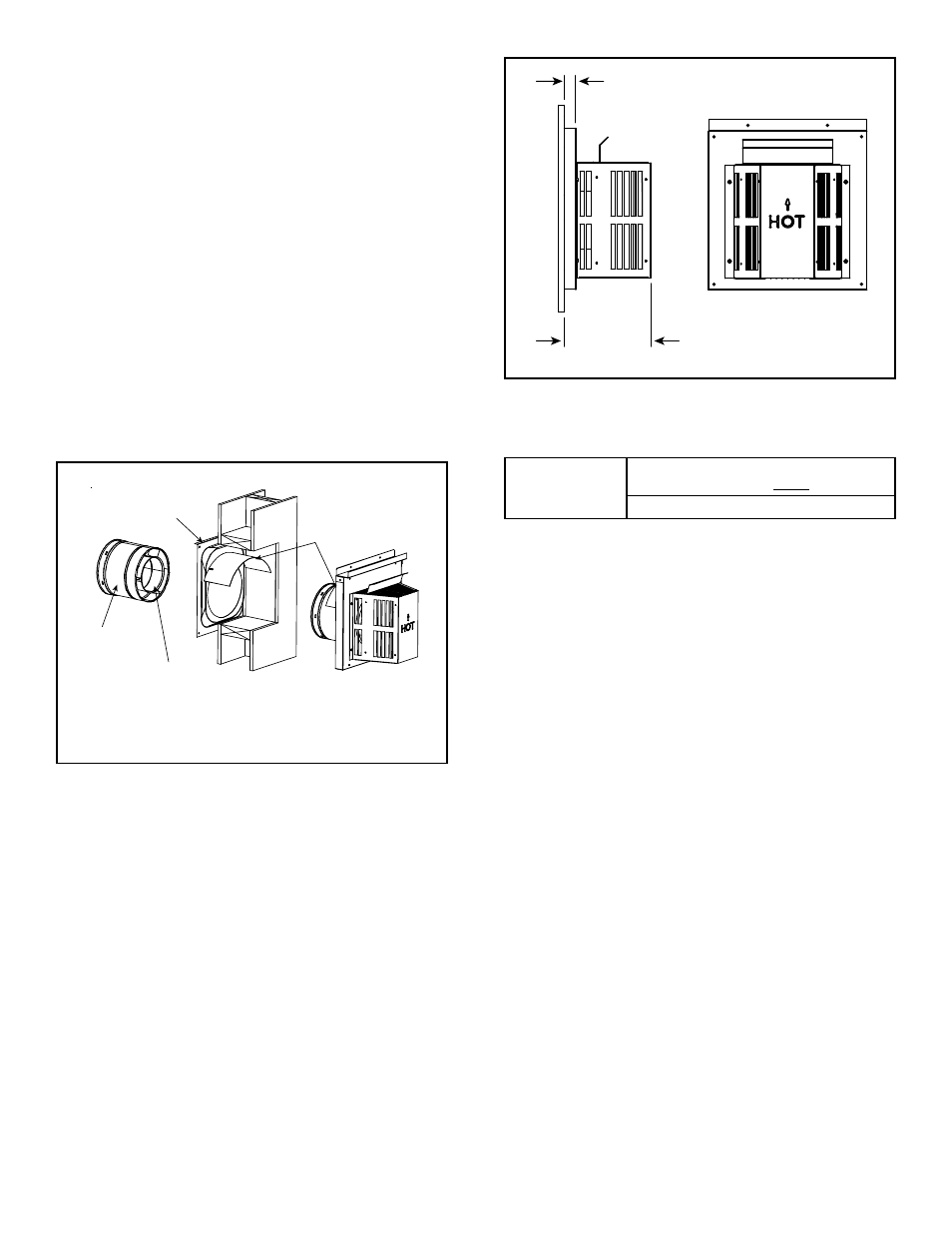
Figure 10.15 Termination Cap
1 in. (25 mm)
7-1/2 in.
(192 mm)
MINIMUM
Cap Specification Chart
(depth without using additional pipe sections)
SOHO-N-AUB
SLP-TRAP2
Rear Vent Depth
5-1/2 in. (139 mm) to 9-1/2 in. (241 mm)
SLP-TRAP2 can adjust 4 in. 102 mm (5-3/8 to 9-3/8) (137 mm to 238
mm)