Service parts list – Hearth and Home Technologies Direct Vent Gas Appliance CNXT4236IT User Manual
Page 58
Heatilator • Caliber CNXT Series • 4047-132 Rev U • 11/08
58
Child Proof Mode
To Enter Child Proof Mode:
• Press the Up Arrow Button twice and Down Arrow Button
once. The unit will send out three beeps and an indicator
in the LCD panel will show that the child proof is on.
To Leave Child Proof Mode:
• Press the Up Arrow Button twice and Donw Arrow
Button once. The unit will send out three beeps and the
indicator in the LCD panel showing that child proof is on
will disappear.
Note: When in Child Proof Mode, only the arrow buttons
will have functionality. Unit can enter Child Proof when
the fi replace is on or off.
Cold Climate Button
• Button Press: Turns on Climate Control
• Button Press: Turns off Climate Control
This allows the pilot fl ame to stay lit when activated. A
benefi t of this is reduced condensation on the glass at
start-up in colder climate conditions.
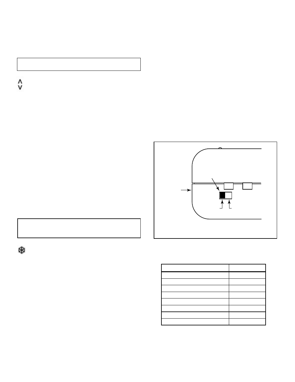
Operation Under Battery Power
A switch on the control box allows for battery power
under no-power conditions (see Figure 12.9). By control-
ling the power supply with this switch, the batteries are
supplying power only when needed, thus extending bat-
tery life. The switch also provides a convenient means for
switching to battery power should there be a loss of 110
VAC power to the control box.
• In the event of a power failure, switch the battery
operation switch to the “Battery ON” position.
• The
fi replace can now be turned on and off with the
ON/OFF rocker switch located near the gas valve.
• The wall switch functions will not operate under battery
power.
• Under battery control the only available function is fl ame
“ON” and “OFF” in the high position.
• To maximize battery life, and to restore full function
capability of the wall switch, fl ip switch to “OFF” position
after 120 VAC power is restored.
SET Set Temperature Button
• Button Press: Displays Set Point
• Use UP and Down Arrows to adjust set point
• Press Set Button to store new set point
Temperature Set Point can be adjusted between the rang-
es of 45-90° Fahrenheit or 7-32° Centigrade.
Note: The controller will turn off the fi replace at 2° F over
set point and turn it back on at 2° F below set point.
Up and Down Arrows
• Push to adjust set point temperature under automatic
control.
AUX Auxilary
Button
• Button Press: Turns on auxilary power
• Button Press: Turns off auxilary power
Can be operated independently of all functions.
Control
Box
"OFF"
Position
"Battery On"
Position
Battery
Operation
Switch
Figure 12.9 Control Box
Service Parts List
Description
Service Part #
Solenoid
HTI-17-006
Wall Switch/Key Pad
HTI-12-007
Cover Plate
HTI-21-007
Control Box
HTI-13-007
Actuator Pins
HTI-17-116
Switch Kit
060-511
Wire Assy Male Terminals
4003-128
Wire Assy 1-Male/1-Female Terminal
4003-129