Framing and clearances, A. selecting appliance location – Hearth and Home Technologies Direct Vent Gas Appliance CNXT4236IT User Manual
Page 17
Heatilator • Caliber CNXT Series • 4047-132 Rev U • 11/08
17
5
5
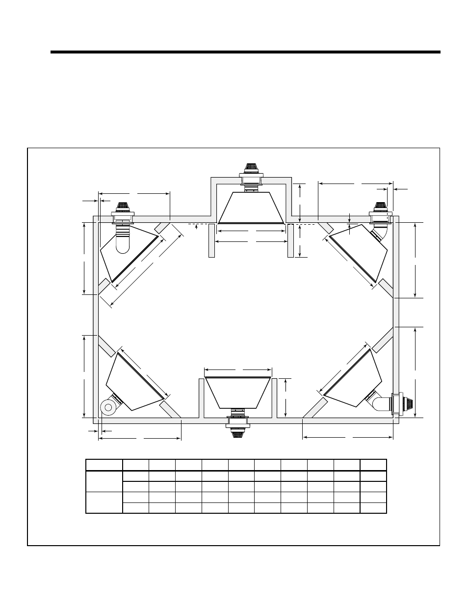
Framing and Clearances
A. Selecting Appliance Location
When selecting a location for the appliance it is important
to consider the required clearances to walls (see Figure
5.1).
WARNING! Risk of Fire or Burns! Provide adequate
clearance around air openings and for service access. Due
to high temperatures, the appliance should be located out
of traffi c and away from furniture and draperies.
NOTICE: Illustrations refl ect typical installations and are
FOR DESIGN PURPOSES ONLY. Illustrations/diagrams
are not drawn to scale. Actual installation may vary due to
individual design preference.
In addition to these framing dimensions, also reference the
following sections:
• Clearances and Mantel Projections (Section 3.C.)
• Vent Clearances and Framing (Section 6)
Rear vent
One 45° elbow
Horiz Term
Rear Vent
Two 90° elbows
Horiz Term
Rear Vent
One 90° elbow
Vert Term
Top Vent
One 90° elbow
Horiz Term
No elbows
Horiz Term
A
A
A
G
A
A
C
D
B
B
F
1 in. (25 mm) min.
pipe to combustibles
I
E
1/2 in. (13 mm) min.
appliance to
combustibles
E
I
1 in. (25 mm) min
pipe to
combustibles
F
1/2 in. (13 mm) min.
appliance to
combustibles
Alcove
Installation
C
H
Drywall
A
Figure 5.1 Appliance Locations
Model #
A
B
C
D
E
F
G
H
I
CNXT4236
in.
42
50 5/8
23
71 5/8
50 5/8
52 5/8
43
48
59 3/4
mm
1067
1286
584
1819
1286
1337
1092
1219
1518
CNXT4842
in.
48
55 1/4
23
78 1/4
55 1/4
55 1/4
49
48
59 3/4
mm
1219
1403
584
1988
1403
1403
1245
1219
1518