Electrical information – Hearth and Home Technologies Direct Vent Gas Appliance CNXT4236IT User Manual
Page 52
Heatilator • Caliber CNXT Series • 4047-132 Rev U • 11/08
52
12
12
Electrical Information
A. Wiring Requirements
NOTICE: This appliance must be electrically wired
and grounded in accordance with local codes or, in the
absence of local codes, with National Electric Code
ANSI/NFPA 70-latest edition or the Canadian Electric
Code CSA C22.1.
• A 110-120 VAC circuit for this product must be protected
with ground-fault circuit-interrupter protection, in
compliance with the applicable electrical codes, when
it is installed in locations such as in bathrooms or near
sinks.
• Wire the appliance junction box to 110-120 VAC. This is
required for use of optional accessories (standing pilot
ignition) or proper operation of the appliance (Intellifi re
ignition).
• Low voltage and 110 VAC voltage cannot be shared
within the same wall box.
• This appliance is inoperable without the WSK-MLT Multi-
Function Wall Switch supplied with the appliance.
• See Section D for locating the wall switch to ensure
proper operation of the appliance.
• Use low resistance thermostat wire for wiring from
ignition system to the wall switch and thermostat.
• Keep wire lengths short as possible by removing any
excess wire length.
WARNING! Risk of Shock or Explosion! DO NOT wire
110V to the valve or to the appliance wall switch. Incorrect
wiring will damage controls.
B. Intellifi re Ignition System Wiring
• Wire the appliance junction box to 110 VAC for proper
operation of the appliance.
WARNING! Risk of Shock or Explosion! DO NOT wire
IPI controlled appliance junction box to a switched circuit.
Incorrect wiring will override IPI safety lockout.
• Refer to Figure 12.2, Intellifi re Pilot Ignition (IPI) Wiring
Diagram.
• This appliance is equipped with an Intellifi re control valve
which operates on a 3 volt system.
• Plug the 3-volt AC transformer into the appliance junction
box to supply power to the unit OR install two D cell
batteries (not included) into the battery pack before
use.
NOTICE: Batteries should not be placed in the battery
pack while using the transformer. Remove batteries before
using the transformer, and unplug the transformer before
installing the batteries. Battery polarity must be correct or
module damage will occur.
C. Electrical Service and Repair
WARNING! Risk of Shock! Label all wires prior to
disconnection when servicing controls. Wiring errors can
cause improper and dangerous operation. Verify proper
operation after servicing.
WARNING! Risk of Shock! Replace damaged wire with
type 105° C rated wire. Wire must have high temperature
insulation.
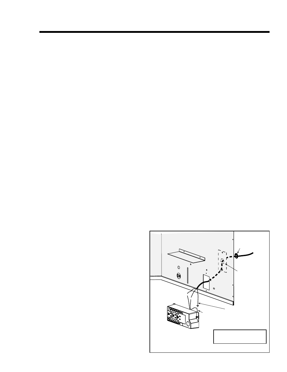
WHT
WH
T
BLK
BLK
GRN wire
inside box
Copper
ground attached
to GRN screw with
GRN wire
14/2WG
Cover Plate
outside firebox
Romex
Connector
Figure 12.1 Junction Box Detail
D. Junction Box Installation
If the box is being wired from the OUTSIDE of the appli-
ance:
• Remove the cover plate located on the outer shell - right
side (see Figure 12.1).
• Install the supplied Romex™ connector in the cover
plate.
• Make all necessary wire connections and reattach the
cover plate to the outer shell.
If the box is being wired from the INSIDE of the appli-
ance:
• Remove the screw attaching the junction box/receptacle
to the outer shell, rotate the junction box inward to
disengage it from the outer shell.
• Pull the electrical wires from outside the appliance through
this opening into the valve compartment.
• Feed the necessary length of wire through the
connector.
• Make all necessary wire connections to the junction box/
receptacle and reassemble the junction box/receptacle
to the outer shell.
NOTICE: DO NOT wire
110 VAC to wall switch.