M. install horizontal termination cap – Hearth and Home Technologies Direct Vent Gas Appliance CNXT4236IT User Manual
Page 50
Heatilator • Caliber CNXT Series • 4047-132 Rev U • 11/08
50
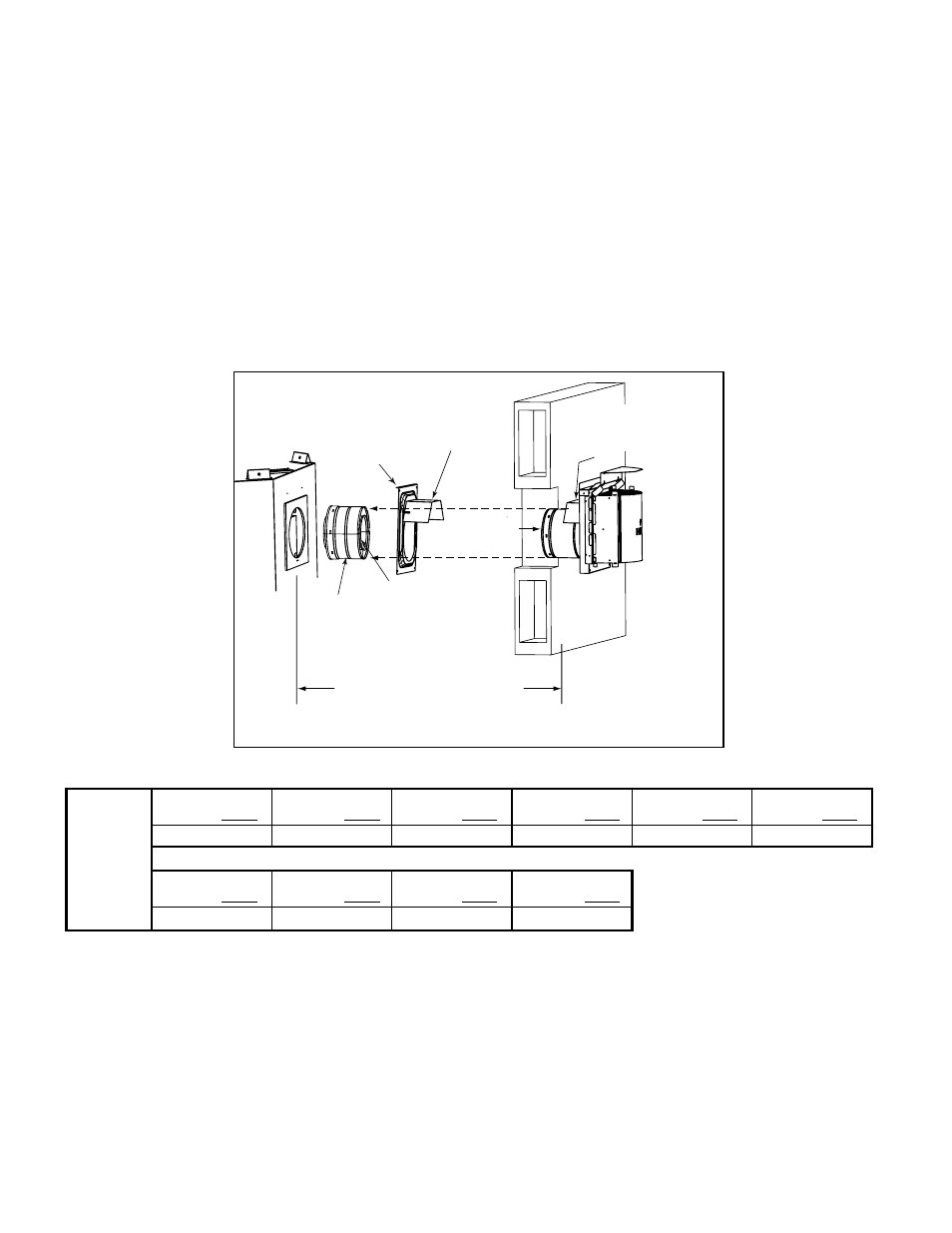
Figure 10.26 Venting through the wall
Note: When using termination caps with factory-supplied
heat shield attached, no additional wall shield fi restop is
required on the exterior side of a combustible wall.
M. Install Horizontal Termination Cap
WARNING! Risk of Fire! The telescoping fl ue section
of the termination cap MUST be used when connecting
vent.
• 1-1/2 (38 mm) minimum overlap of fl ue telescoping
section is required.
Failure to maintain overlap may cause overheating and
fi re.
• Vent termination must not be recessed in the wall. Siding
may be brought to the edge of the cap base.
• Flash and seal as appropriate for siding material at
outside edges of cap.
INTERIOR
Heat Shield or
Extended
Heat Shield
Wall Shield
Firestop
Heat Shield
1-1/2 in. (38 mm) min.
overlap
SHEATHING
Vent depth from back of appliance to
outside surface of exterior wall
(see chart below)
Slip Section
can be extended
Inner Vent
Outer Vent
EXTERIOR
• When installing a horizontal termination cap, follow
the cap location guidelines as prescribed by current
ANSI Z223.1 and CAN/CGA-B149 installation codes
and refer to Section 6 of this manual.
CAUTION! Risk of Burns! Local codes may require
installation of a cap shield to prevent anything or anyone
from touching the hot cap.
NOTICE: For certain exposures which require superior
resistance to wind-driven rain penetration, a fl ashing kit and
HRC caps are available. When penetrating a brick wall, a
brick extension kit is available for framing the brick.
Cap Specifi cation Chart (depth without using additional pipe sections)
CNXT Series
DVP-TRAPK1
Top Vent Depth
DVP-TRAP1
Rear Vent Depth
DVP-TRAPK2
Top Vent Depth
DVP-TRAP2
Rear Vent Depth
DVP-TRAPK1
Top Vent Depth
DVP-TRAPK2
Top Vent Depth
4-1/8 to 6 in.
4-5/8 to 6-1/2 in.
6-1/2 to 10-1/2 in.
7 to 11 in.
1 5/8 to 3 1/2 in.
4 to 8 in.
DVP-HPC1
Top Vent Depth
DVP-HPC1
Rear Vent Depth
DVP-HPC2
Top Vent Depth
DVP-HPC2
Rear Vent Depth
4-1/8 to 6-1/4 in.
4-5/8 to 6-3/4 in.
6-1/4 to 10-3/8 in.
6-3/4 to 10-7/8 in.
DVP-TRAP1 can adjust 1-7/8 in. (4-3/16 to 6-1/16)
DVP-TRAP2 can adjust 4 in. (6-9/16 to 10-9/16)
SLP-TRAP1 can adjust 1 5/8 in. (3 1/8 to 4 3/4)
SLP-TRAP2 can adjust 4 in. (5 1/4 to 9 1/4))
DVP-HPC1 can adjust 2-1/8 in. (4-1/4 to 6-3/8)
DVP-HPC2 can adjust 4-1/8 in. (6-3/8 to 10-1/2)