Vent clearances and framing, A. pipe clearances to combustibles, B. wall penetration framing – Heat & Glo Fireplace VRT-BZ-P-AUB User Manual
Page 37
37
Heat & Glo • VRT-AUB • 2123-980 Rev. J • 2/13
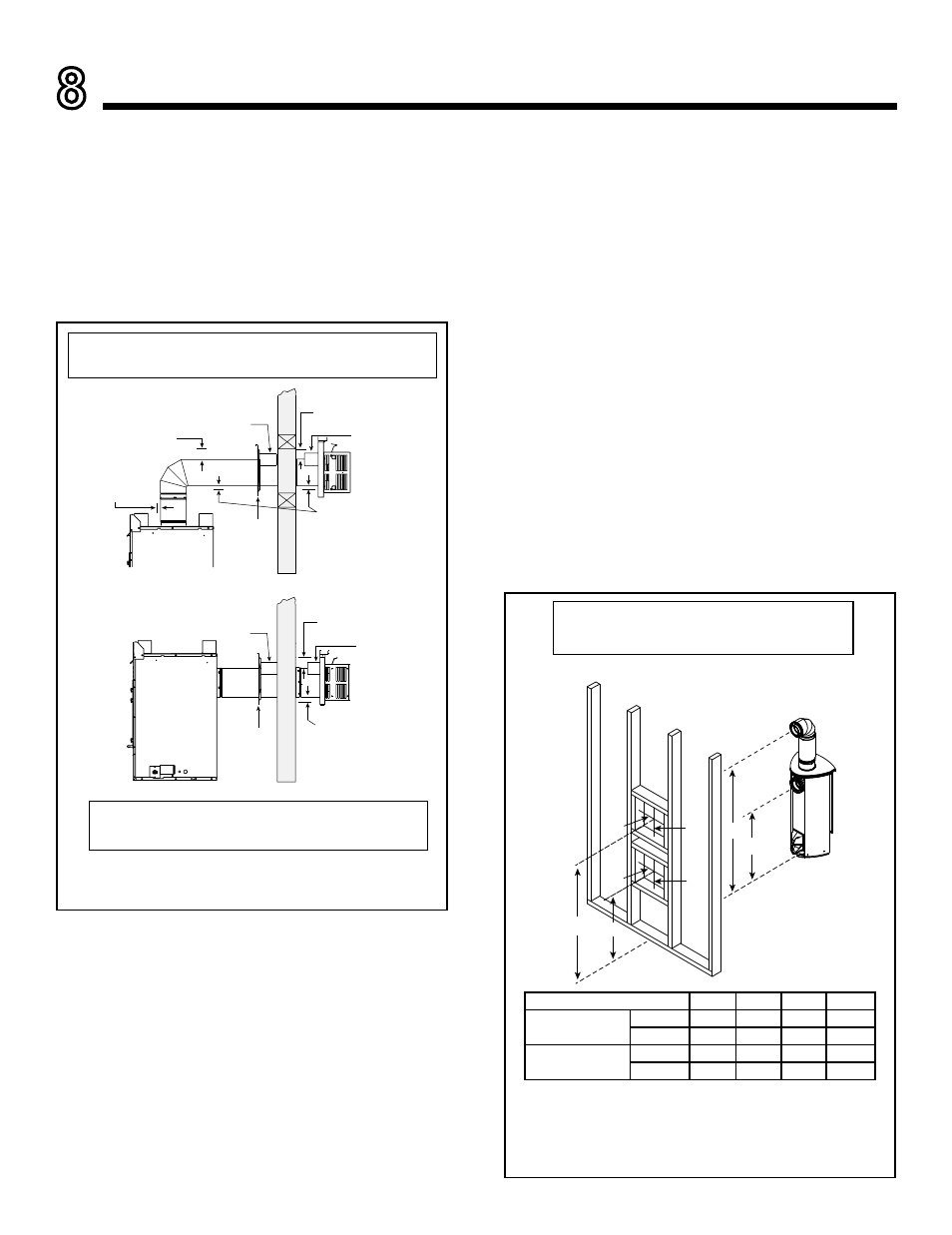
A. Pipe Clearances to Combustibles
WARNING! Risk of Fire! Maintain air space clearance to
vent.
DO NOT pack insulation or other combustibles:
• Between ceiling firestops
• Between wall shield firestops
• Around vent system
Failure to keep insulation or other material away from
vent pipe may cause over heating and fire.
8
Vent Clearances and Framing
Figure 8.2 Wall Penetration
* Shows center of vent framing hole for top or rear venting. The center of
the hole is one 1 in. (25.4 mm) above the center of the horizontal vent
pipe.
* Unit shown with 1-1/2 ft. (457.2 mm) of
vertical pipe. Vertical section will vary by gas.
Refer to vent chart for minimum vertical.
C
D
A*
B*
10 in.
(254 mm)
10 in.
(254 mm)
10 in.
(254 mm)
10 in.
(254 mm)
Figure 8.1 Horizontal Venting Clearances To Combustible
Materials
B. Wall Penetration Framing
Combustible Wall Penetration
Whenever a combustible wall is penetrated, you must
frame a hole for the wall shield firestop(s). The wall shield
firestop maintains minimum clearances and prevents cold
air infiltration.
• The opening must be framed on all four sides using the
same size framing materials as those used in the wall
construction.
• SLP pipe - A wall shield firestop must be placed on each
side of an interior wall. A minimum 1-1/2 inch (38 mm)
overlap of attached heat shields must be maintained.
• See Section 10.H for information for regarding the in-
stallation of a horizontal termination cap.
Non-Combustible Wall Penetration
If the hole being penetrated is surrounded by noncom-
bustible materials such as concrete, a hole with diameter
one inch greater than the pipe is acceptable.
Whenever a non-combustible wall is penetrated, the wall
shield firestop is only required on one side and no heat
shield is necessary.
Note: A 6 in. (152 mm) section of straight flue
must be attached to the fireplace before a 90°
elbow.
A*
B*
C
D
VRT-N-AUB
Inches
69.3 34-3/4 68.3
33-3/4
Millimeters
1761
883
1736
857
VRT-P-AUB
Inches
69.3 34-3/4 68.3
33-3/4
Millimeters
1761
883
1736
857
* When using SLP pipe, minimum clearances from the vent pipe to combustible
materials at inside wall firestops are:
Top: 2-1/2 in. (64 mm)
Bottom: 1/2 in. (13 mm)
Sides: 1 in. (25 mm)
3 in. (76 mm)
top clearance *
1 in. (25 mm)
clearance
bottom & sides
Heat
Shield
Wall
Shield
Firestop
Heat
Shield
WALL
Heat
Shield
Wall
Shield
Firestop
Heat
Shield
WALL
3 in. (76 mm)
top clearance
1 in. (25 mm)
clearance around
vertical sections
Note: Heat shields MUST overlap by a minimum of 1-1/2 in. (38 mm).
• If wall thickness is less than 4 in. (102 mm) the existing heat shields must be field
trimmed.
3 in. (76 mm)
top clearance *
1 in. (25 mm)
clearance
bottom & sides