Warning – Heat & Glo Fireplace VRT-BZ-P-AUB User Manual
Page 31
31
Heat & Glo • VRT-AUB • 2123-980 Rev. J • 2/13
Step 2.
For installations using a round support box/wall thimble
(check pipe manufacturer's instructions), mark the wall for
a 9 in. x 9 in. (229 mm x 229 mm) square hole. The center
of the square hole should line up with the center line of
the horizontal pipe. Cut and frame the hole in the exterior
wall where the flue will be terminated. If the wall being
penetrated is constructed of noncombustible material, i.e.
masonry block or concrete, a 7 in. (178 mm) diameter
hole is acceptable.
Step 3.
Position the horizontal termination cap in the center of the
9 in. x 9 in. (229 mm x 229 mm) square hole and run a
bead of non-hardening mastic around its outside edges,
to make a seal between it and the wall. Attach termination
cap to the exterior wall with the four wood screws pro-
vided. The arrow on the flue cap should be pointing up.
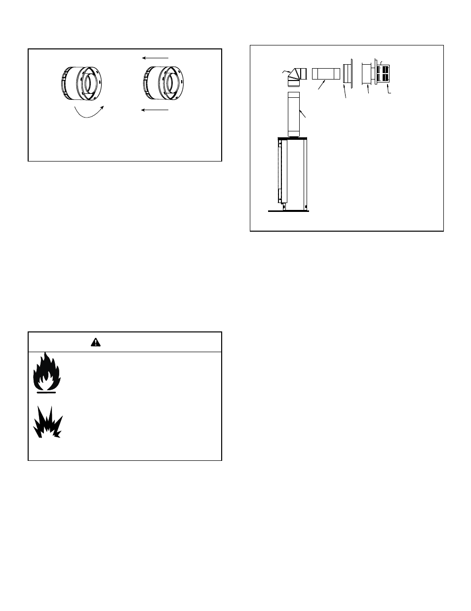
Figure 7.13
Figure 7.12
Note: Align seams to engage pipe,
then rotate counterclockwise to lock
Step 1.
Balanced flue pipe is designed with a locking connection.
To connect the flue system to the gas stove flue outlet:
• Lock the flue components into place by sliding the pipe
section onto the collar.
• Align the seam of the pipe and seam of collar to allow
engagement. Rotate the flue component to lock into
place. Use this procedure for all flue components. See
Figure 7.12.
• Continue adding flue components, locking each
succeeding component into place.
• Ensure that each succeeding flue component is securely
fitted and locked into the preceding component.
90 DEGREE
ELBOW
PIPE LENGTH
PIPE LENGTH
WALL THIMBLE
COVER
WALL THIMBLE
TERMINATION CAP
Fire Risk.
Explosion Risk.
Combustion Fume Risk.
Use flue run supports per installation instructions.
Connect flue sections per installation instructions.
• Maintain all clearances to combustibles.
• Do NOT allow flue to sag below connection
point to gas stove.
• Maintain specified slope (if required).
WARNING
Improper support may allow flue to sag or separate.
E. Flue Pipe Assembly
F. Horizontal Penetration Framing