Ase connection diagram, Drg. no, Ase connection – Honeywell NOTIFIER IFS-2600 User Manual
Page 62
Page 58
IFS-2600 Installation & Programming Manual
P/N 10069 ECN08-0066
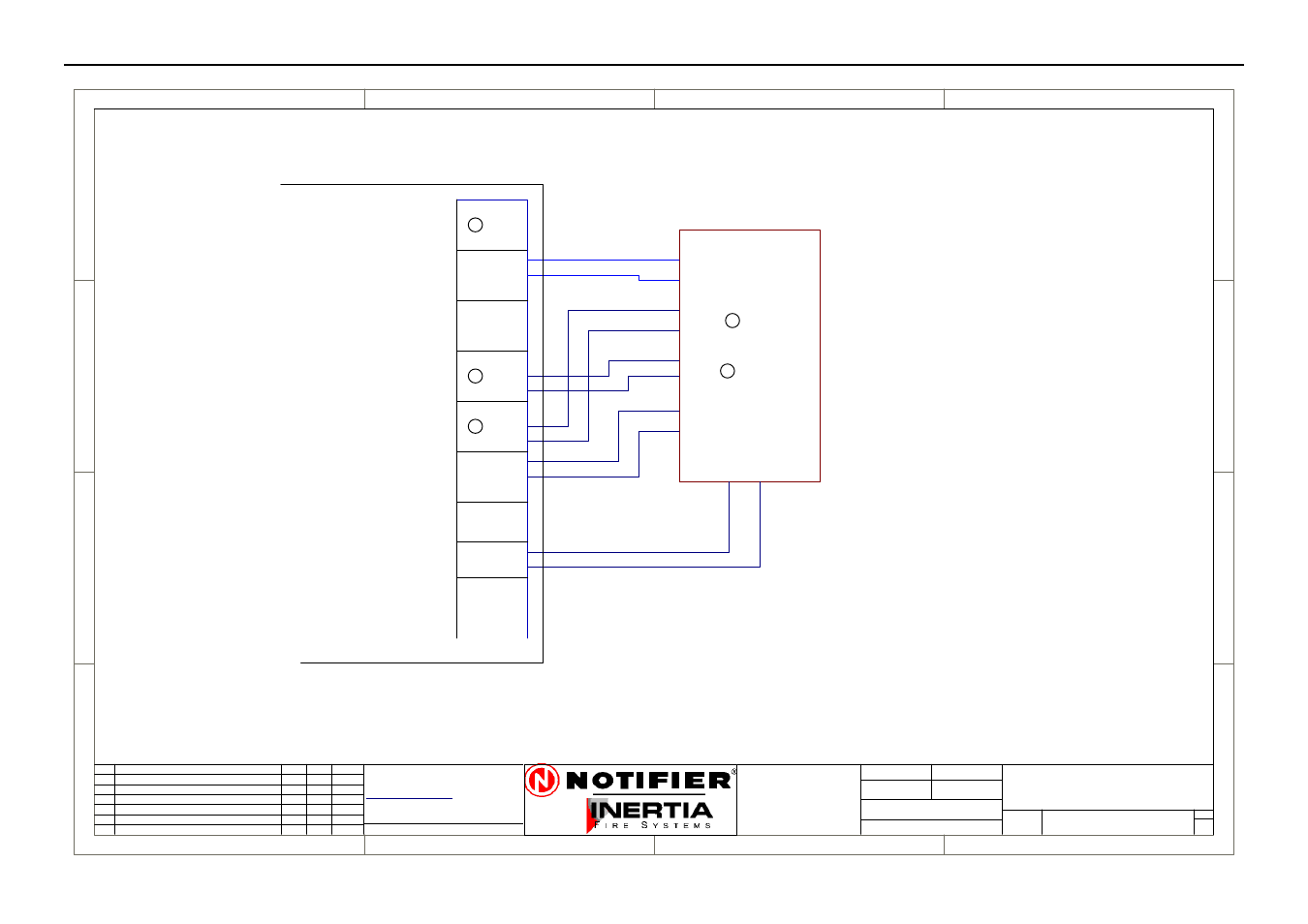
ASE Connection Diagram
1
1
2
2
3
3
4
4
D
D
C
C
B
B
A
A
Rev
Size
Drg.
No.
Title
Sheet:
Drawn/
Traced
Engineer
Design
Approved
This Drawing must not be used for Construction
unless signed as approved
7 Columbia Court,
Norwest Business Park
Baulkham Hills NSW 2153
AUSTRALIA
Tel
Fax
Email: [email protected]
A4
No.
Revision - revise on CAD. Do not amend by hand Eng.
App.
Date
Copyright
This document is & shall
remain the property of
Notifier Inertia Fire Systems
Unauthorised use of this
document in any way is
prohibited.
Drawing File No.
C
O
61 2 9894 1444
61 2 9899 4156
=DocumentFullPathAndName
Of:
2600
S
T
A
N
D
B
Y
N/C
COM
N/O
B
R
IG
A
D
E
1
COM
B
R
IG
A
D
E
2
N/C
COM
N/O
F
A
U
L
T
N/O
N/O
N/C
+24
0V
A
U
X
N
IFS2600
N/C
N/O
A
C
-F
A
IL
N/C
COM
N/C
COM
IS
O
L
A
T
E
COM
N/O
ASE CONNECTION
26-ASE
A
1
1
22/8/05
I.P.
ASE
POWER
BRACKET
TYCO #10116
CODE RED #10115
ROMTEK 10117
AC FAIL
BR1
FAULT
ISOLATE
ASE
PCB2004
TERMINATION
N
N
N
N