HP 2000 User Manual
Page 75
73
Replacement Procedure
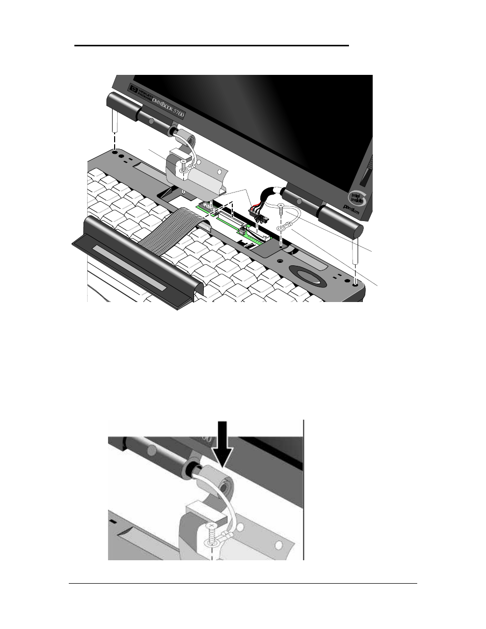
1. To replace, reverse the above Removal Procedure. Take care to properly position the
Display Flex Cable. It must be wrapped three times around the post. See Figure 28.
C
AUTION
:
To avoid crimping the icon assembly flex cable, ensure that it is tucked
inside of the icon assembly “tunnel.”
Figure 27 - Display Cables
Figure 28 - Display Flex Cable Position
Display
Cables
Display
Grounding
Cable
Display
Grounding
Cable
Display/Chassis
Screws
F1081-60939
(qty 2)
See also other documents in the category HP Notebooks:
- EliteBook 8440p (169 pages)
- XZ100 (104 pages)
- ZT1100 (58 pages)
- 110 (104 pages)
- ze2000 (213 pages)
- OmniBook 2000 Notebook PC (70 pages)
- XE3 (116 pages)
- 1103 (101 pages)
- ze4200 (126 pages)
- TC1 100 (17 pages)
- 15 (101 pages)
- XB4000 (43 pages)
- ze2300 (239 pages)
- Laptop Docking Station (70 pages)
- VXI E1432A (222 pages)
- V6115TU (22 pages)
- 210 (67 pages)
- zt3000 (186 pages)
- XB3000 (79 pages)
- xe310 (12 pages)
- COMPAQ TC4400 (219 pages)
- 367055-002 (26 pages)
- Compaq Tablet PC TC1 100 (23 pages)
- 463777-001 (42 pages)
- zx5000 (272 pages)
- VC133 (38 pages)
- USB Media Docking Station VY847AA#ABA (1 page)
- ze4100 (5 pages)
- ZE4900 (182 pages)
- V4200 (273 pages)
- Compaq Tablet PC TC1100HP (22 pages)
- EliteBook 6930p Notebook PC (35 pages)
- Chromebook 11 G2 (23 pages)
- EliteBook Folio 9470M-Notebook-PC (33 pages)
- EliteBook 2570p Notebook PC (107 pages)
- EliteBook 2570p Notebook PC (106 pages)
- ProBook 6470b Notebook-PC (113 pages)
- ProBook 6470b Notebook-PC (126 pages)
- EliteBook 2540p Notebook PC (175 pages)
- EliteBook 2540p Notebook PC (173 pages)
- EliteBook 2540p Notebook PC (177 pages)
- EliteBook 2540p Notebook PC (23 pages)
- ProBook 6460B Notebook-PC (45 pages)
- mt41 Mobile Thin Client (90 pages)