HP Vectra VL 5/xxx Series 5 User Manual
Page 59
59
3 Interface Devices and Mass-Storage Drives
Connectors and Sockets
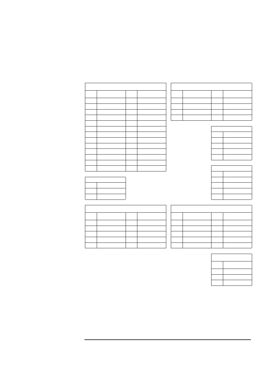
Audio Board Connectors
Wavetable Connector
Goldfinch Connector
Pin
Signal
Pin
Signal
Pin
Signal
Pin
Signal
1 Ground
2 not connected
1 Line-in (right)
2 Analog ground
3 Ground
4 MIDI input
3 Line-in (left)
4 Analog ground
5 Ground
6 Vcc
5 orientation key
6 Analog ground
7 Ground
8 MIDI output
7 Analog ground
8 Analog ground
9 Ground
10 Vcc
11 Ground
12 not connected
Aux2 MPEG Connector
13 not connected
14 Vcc
Pin
Signal
15 Ground
16 not connected
1 Left channel
17 Ground
18 +12 V
2 Ground
19 Ground
20 Line-in (right)
3 Ground
21 Ground
22 -12 V
4 Right channel
23 Ground
24 Line-in (left)
25 Ground
26 Reset B
CD Audio Connector
Pin
Signal
Int. Speaker Connector
1 Ground
Pin
Signal
2 Left channel
1 Power signal out
3 Ground
2 Analog ground
4 Right channel
Modem Connector
Front Panel Connector
Pin
Signal
Pin
Signal
Pin
Signal
Pin
Signal
1 Analog ground
2 orientation key
1 Ground
2 orientation key
3 Line-in
4 Analog ground
3 Headphones left
4 Head return left
5 Line-out (left)
6 Analog ground
5 Headphones right
6 Head return right
7 Line-out (right)
8 Modem speaker
7 Volume low limit
8 Volume DC cntl
9 Analog ground
10 Microphone in
9 Volume high limit
10 not used
Microphone Connector
Pin
Signal
2nd ring:
3 Signal and power
3rd ring:
2 Ground
1st ring:
1 Signal and power