HP Vectra VL 5/xxx Series 5 User Manual
Page 39
39
2 System Board
Devices on the ISA Bus
System Board Switches
Five of the system board switches (whose location is shown on page 20) set
the working frequencies for the computer, as summarized on page 31. The
others set the configuration for the computer, as summarized in the table on
the next page.
By setting switch SW6 in the
Closed
position, not only is the configuration
data cleared (in the CMOS memory and the Serial EEPROM), but also all the
Plug-and-Play data that had been saved in the Serial EEPROM. However,
the serial number, the tattooing string, the date and the time are each
retained.
By setting switch SW9 in the
Closed
position, the Power-On Space-Bar
function is enabled. Note, though, that it must also be enabled in the
Power-On Space-Bar
field of the Power Menu in the Setup program.
Turning the computer on, with switch SW10 in the
Closed
position, clears
the product identification field in the BIOS, and causes the computer to
prompt for the new information. By identifying the product correctly (after
replacing a defective system board by a new one), the BIOS is able to tailor
itself for the particular product, and to enable the appropriate features.
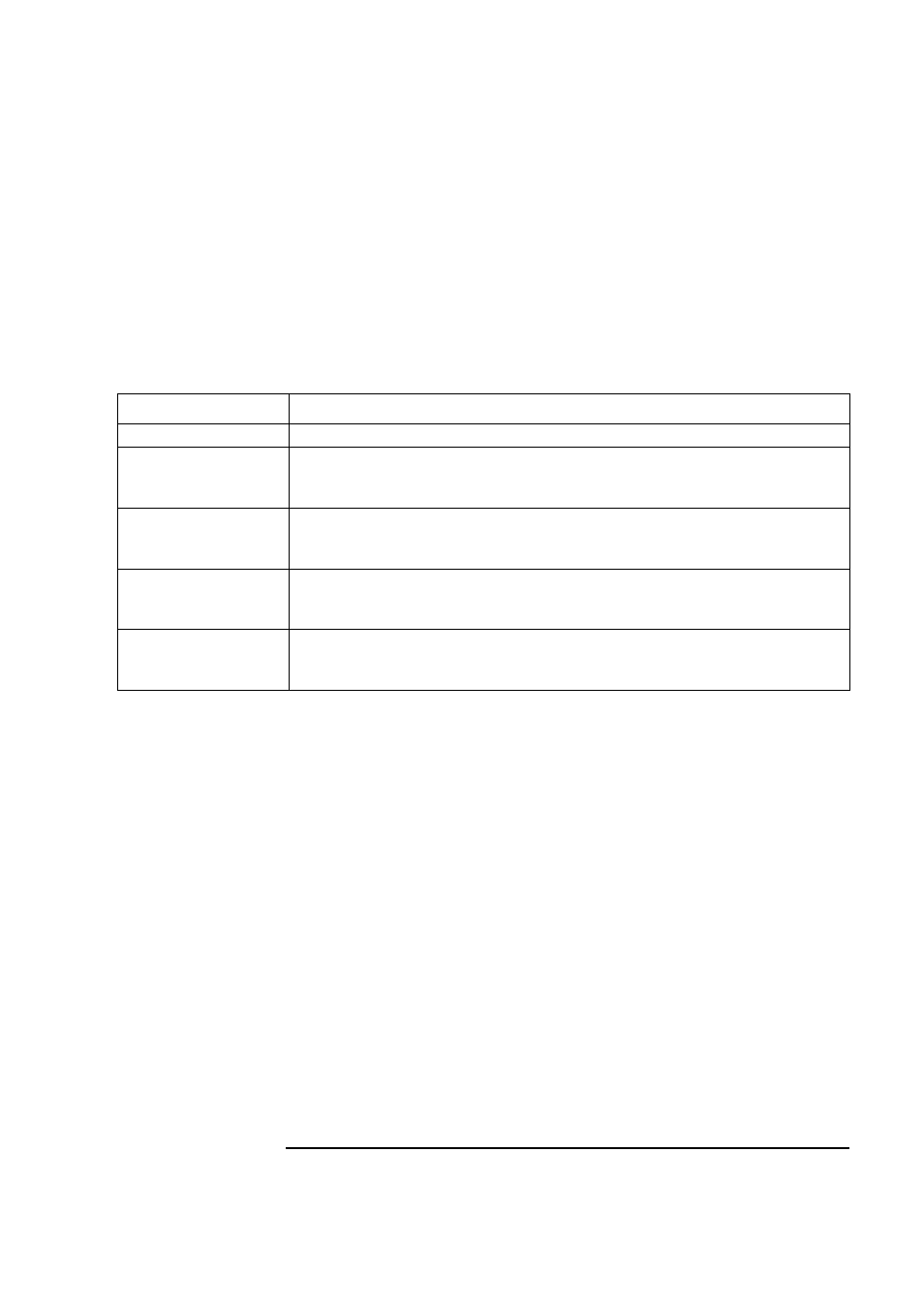
Switch
Functions of the System Board Switches
1-4,7-8
Bus frequencies (see the table on page 31)
5
Password:
Open = enabled (default)
Closed = disabled / clear User and Administrator passwords
6
Clear CMOS:
Open = normal (default)
Closed = clear CMOS (to reload the Setup program defaults)
9
Keyboard space-bar power-on:
Open = disabled
Closed = enabled (default)
10
Product identification:
Open = normal operation (default)
Closed = clear the product identification field in the CMOS memory