Enterasys Networks Enterasys Gold Distributed Forwarding Engine 4H4284-49 User Manual
Page 82
Memory Locations and Replacement Procedures
B-8 Mode Switch Bank Settings and Optional Installations
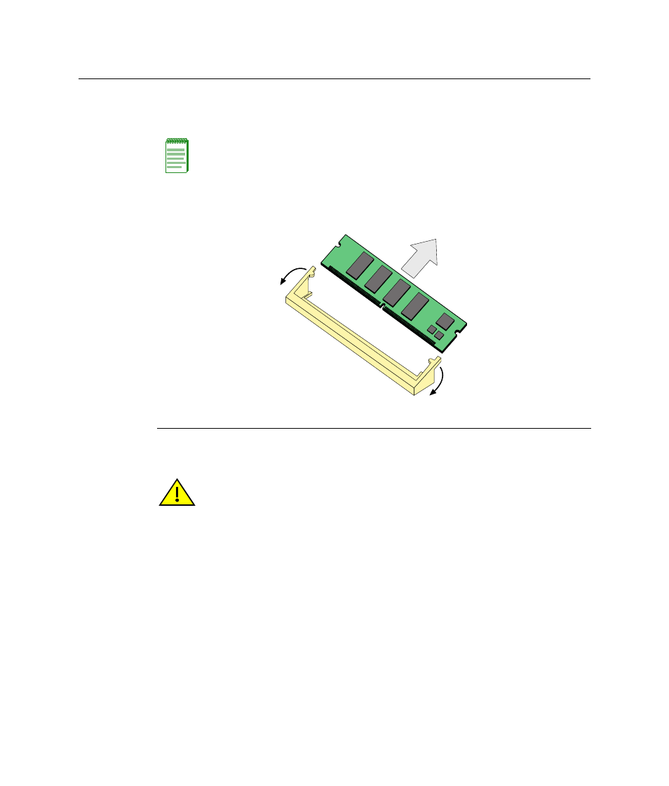
2.
Refer to
. Push the connector arms away from the memory module to
release it from the connector.
3.
Remove the module from the connector.
Installing the DRAM SIMM on 4H4282-49 or 4H4283-49
To install the memory module, refer to
1.
With the connector arms set in the open position, insert the memory module between
the connector fingers and push the memory module into the connector until the tabs
on the two connector arms pull in towards the DRAM SIMM alignment notches.
2.
Push the DRAM SIMM further into the connector until the two alignment notches and
the tabs on the two connector arms lock the DRAM SIMM into place.
Note: The ejector arms on this connector are not spring loaded, so they will remain in the
open position until manually closed.
Figure B-9 Removing the Existing DRAM SIMM from 4H4282-49 or 4H4283-49
1 Connector arms
2 Memory module
3 Connector
В
А
А
Б
Caution: Observe all Electrostatic Discharge (ESD) precautions when handling sensitive
electronic equipment.
Precaución: Al trabajar con equipos electrónicos sensibles, tome todas las precauciones
de seguridad para evitar descargas de electricidad estática.