Instruction manual, Table 6. style h mounting dimensions – Emerson Process Management 1051 User Manual
Page 9
Instruction Manual
D100320X012
1051 and 1052 H & J Actuators
October 2012
9
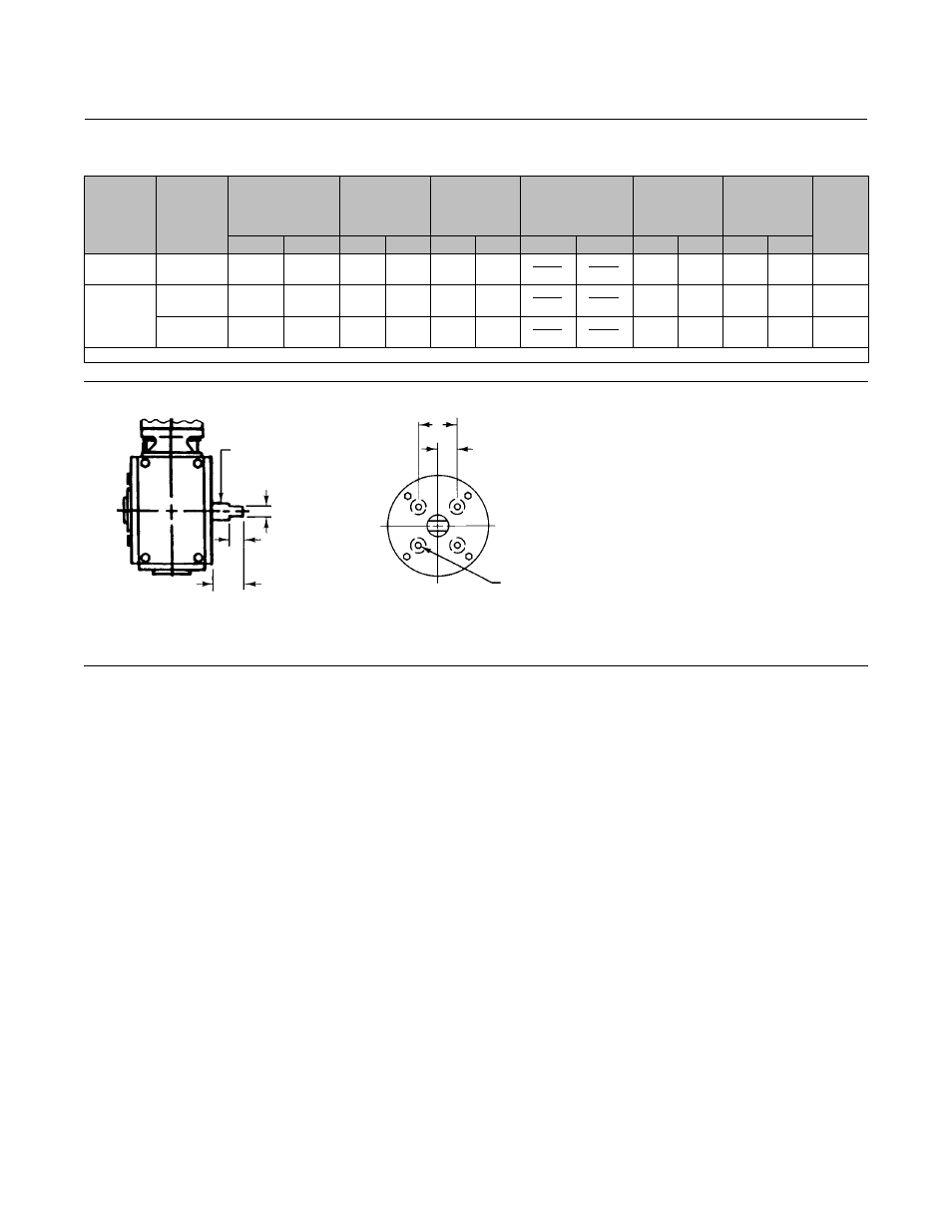
Table 6. Style H Mounting Dimensions
ACTUATOR
SIZE 1051
ACTUATOR
SIZE 1052
S
ACTUATOR
OUTPUT SHAFT
DIAMETER
V
L
K
(1)
T
U
W
mm
Inch
mm
Inch
mm
Inch
mm
Inch
mm
Inch
mm
Inch
40
40
22.2
7/8
26.2
1.03
19.1
0.75
15.75
15.62
0.620
0.615
57.2
2.25
28.4
1.12
5/16-18
UNC
40 & 60
40 & 60
28.6
1-1/8
26.2
1.03
19.1
0.75
22.10
21.97
0.870
0.865
76.2
3.00
38.1
1.50
3/8-16
UNC
40, 60 & 70
38.1
1-1/2
28.4
1.50
28.4
1.12
28.45
28.32
1.120
1.115
88.9
3.50
44.5
1.75
1/2-13
UNC
1. Tolerance for the K dimension is indicated by showing maximum and minimum dimensions.
Figure 6. Fisher 1051 and 1052 Style H Mounting Dimensions (refer to table 6)
22.2 THRU 38.1 mm
(7/8 THRU 1-1/2 INCH)
OUTPUT SHAFTS WITH
STYLE H MOUNTING
22.2 THRU 38.1 mm
(7/8 THRU 1-1/2 INCH)
OUTPUT SHAFTS WITH
STYLE H MOUNTING
S (DIA)
K
L
V
T
U
W (DIA)
19A1461-D
A4997
19A1459-B
A3254-1