Top-mounted handwheel (figure 15), Instruction manual, Figure 15. top-mounted handwheel assemblies – Emerson Process Management 1051 User Manual
Page 34
Instruction Manual
D100320X012
1051 and 1052 H & J Actuators
October 2012
34
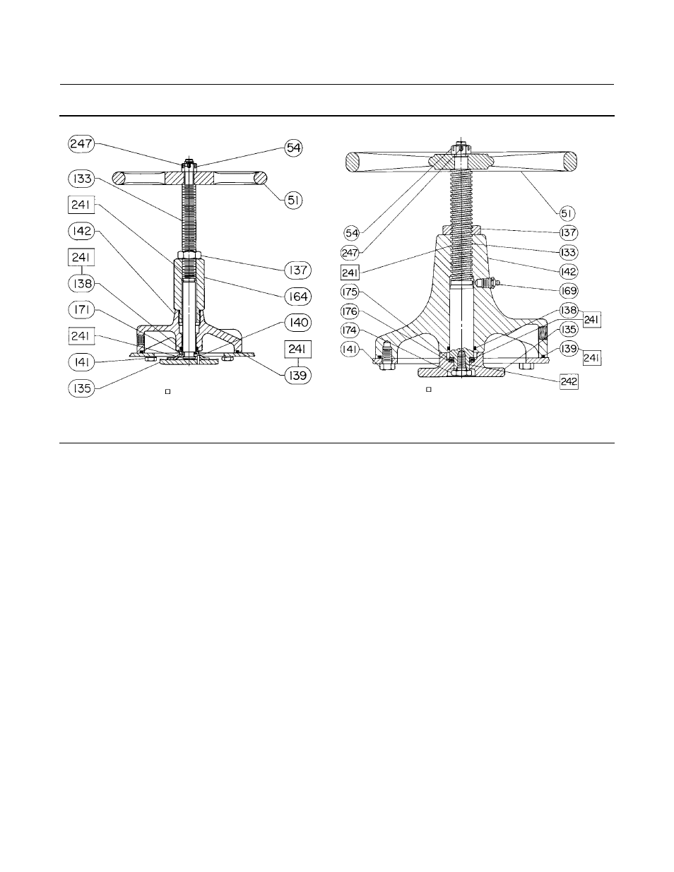
Figure 15. Top-Mounted Handwheel Assemblies
38A1213-B
CV8010-E
TOP-MOUNTED HANDWHEEL ASSEMBLY FOR
SIZE 30, 40, AND 60 ACTUATORS
TOP-MOUNTED HANDWHEEL ASSEMBLY FOR
SIZE 70 ACTUATORS
APPLY LUB
APPLY LUB / SEALANT
Key
Description
Part Number
w/19.1 mm (3/4-inch)
actuator output shaft
G1232232992
w/25.4 mm (1-inch)
actuator output shaft
G1232232992
Style J
Size 60
w/38.1 mm (1-1/2 inch)
Actuator Output Shaft
G1232332992
Sizes 60 & 70
w/50.4 mm (2-inch) actuator output shaft
for 44.5 mm (1-3/4 inch) keyed
equipment shaft
H1361632992
for 50.4 mm (2-inch) keyed
equipment shaft
H1361632992
90
Coupling
91*
Key, Woodruff
See following table
92
Spacer, steel (not shown) (2 req'd)
Sizes 60 & 70 Style J
w/38.1 mm (1-1/2 inch) actuator output shaft
w/31.8 mm (1-1/4 inch) actuator output shaft
- - -
Bushing, Pipe (not shown) (1052 Size 70)
146
Spacer (1 req'd)
Top-Mounted Handwheel (figure
15)
Key
Description
Part Number
51
Handwheel
54
Hex Nut, Slotted
133
Stem
135
Plate, Pusher
137
Hex Nut, Jam, Steel
138* O-Ring, Nitrile
Size 40
1D237506992
Size 60
1B885506992
Size 70
1C415706992
139* O-Ring, Nitrile
Size 40
1D267306992
Size 60
1D547106992
Size 70
1D269106992
140
Groove Pin (Sizes 40 & 60)
141
Cap Screw, Hex hd
Size 40 (6 req'd)
Size 60 (8 req'd)
Size 70 (12 req'd)
142
Body
*Recommended spare parts