Emerson Process Management FISHER 657 User Manual
Emerson Process Management For the car
www.Fisher.com
Fisher
r 657 Diaphragm Actuator
Sizes 30‐70 and 87
Contents
Introduction
1
. . . . . . . . . . . . . . . . . . . . . . . . . . . . . . . . .
Scope of Manual
1
. . . . . . . . . . . . . . . . . . . . . . . . . . . . .
Description
2
. . . . . . . . . . . . . . . . . . . . . . . . . . . . . . . . .
Specifications
2
. . . . . . . . . . . . . . . . . . . . . . . . . . . . . . .
Installation
3
. . . . . . . . . . . . . . . . . . . . . . . . . . . . . . . . . . .
Mounting the Actuator on the Valve
5
. . . . . . . . . . . .
Discussion of Bench Set
6
. . . . . . . . . . . . . . . . . . . . . . .
Spring Verification
7
. . . . . . . . . . . . . . . . . . . . . . . . . . .
Installing the Stem Connector Assembly
8
. . . . . . . . .
Deadband Measurement
8
. . . . . . . . . . . . . . . . . . . . . .
Loading Connection
10
. . . . . . . . . . . . . . . . . . . . . . . . .
Maintenance
10
. . . . . . . . . . . . . . . . . . . . . . . . . . . . . . . .
Actuator Maintenance
11
. . . . . . . . . . . . . . . . . . . . . . .
Top‐Mounted Handwheel Assembly
12
. . . . . . . . . . .
Side‐Mounted Handwheel for Sizes 34
through 60 Actuators
14
. . . . . . . . . . . . . . . . . . . . .
Side‐Mounted Handwheel for Sizes 70
and 87 Actuators
15
. . . . . . . . . . . . . . . . . . . . . . . . .
Casing‐Mounted Adjustable Travel Stops
17
. . . . . . .
Parts Ordering
19
. . . . . . . . . . . . . . . . . . . . . . . . . . . . . . .
Parts Kits
19
. . . . . . . . . . . . . . . . . . . . . . . . . . . . . . . . . . .
Kits for Side‐Mounted Handwheels
19
. . . . . . . . . . . . .
Kits for Top‐Mounted Handwheels
19
. . . . . . . . . . . . .
Parts List
21
. . . . . . . . . . . . . . . . . . . . . . . . . . . . . . . . . . .
Actuator Assembly (figures 6, 7, or 8)
21
. . . . . . . . . .
Top‐Mounted Handwheel (figures 9 or 10)
22
. . . . . .
Side‐Mounted Handwheel (figure 11 or 13)
22
. . . . . .
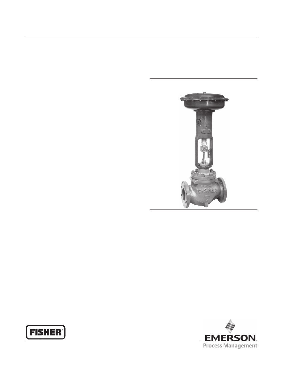
Figure 1. Fisher 657 or 657‐4 Actuator Mounted
on an easy‐e™ Valve
W2174‐2
Casing‐Mounted Adjustable Up Travel Stops
(figures 14 or 15)
26
. . . . . . . . . . . . . . . . . . . . . . . . .
Casing‐Mounted Adjustable Down Travel Stops
(figure 16)
27
. . . . . . . . . . . . . . . . . . . . . . . . . . . . . .
Introduction
Scope of Manual
This instruction manual provides information on installation, adjustment, maintenance, and parts ordering for the
Fisher 657 actuator in sizes 30 through 70 and size 87. The 657‐4 actuator in sizes 70 and 87 is also covered. Refer to
separate instruction manuals for information about the valve positioner and other accessories used with these
actuators.
Instruction Manual
D100306X012
657 Actuator (30-70 and 87)
December 2010