Instruction manual – Emerson Process Management 1051 User Manual
Page 21
Instruction Manual
D100320X012
1051 and 1052 H & J Actuators
October 2012
21
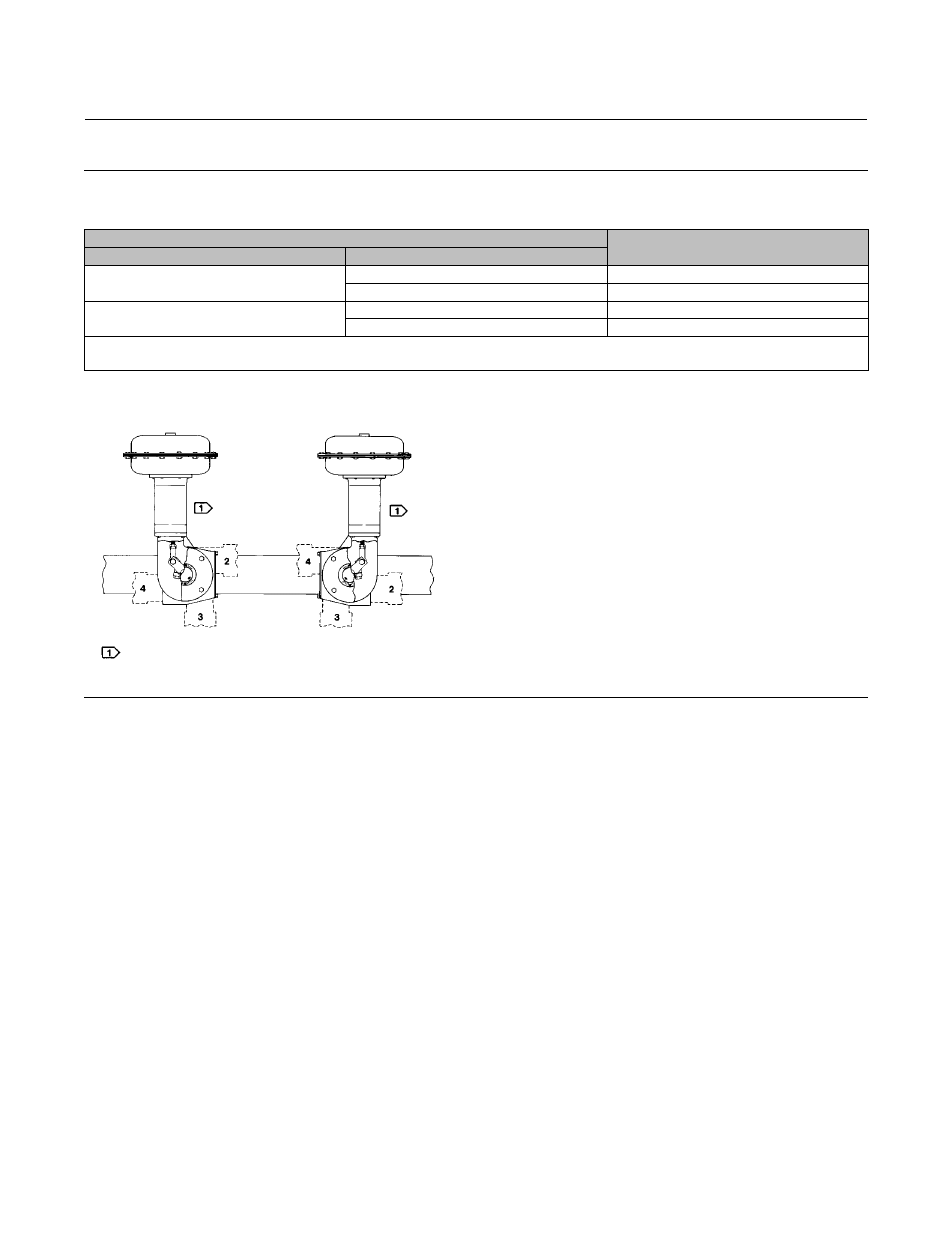
Figure 10. Actuator Housing Construction Styles and Mounting Positions
DESIRED ACTION OF
HOUSING CONSTRUCTION TO SPECIFY
Actuator
Operated Equipment
Push Down to Open
(1)
(PDTO)
Clockwise to Close
(3)
Style A
Counterclockwise to Close
(3)
Style B
Push Down to Close
(2)
(PDTC)
Clockwise to Close
(3)
Style B
Counterclockwise to Close
(3)
Style A
1. This action uses the spring to close the valve body or other equipment.
2. This action uses the spring to open the valve body or other equipment.
3. When viewed from actuator side of valve body or other equipment.
STYLE A
STYLE B
POSITION 1
STANDARD
POSITION 1
STANDARD
NOTE:
DOTTED LINES INDICATE ALTERNATE MOUNTING POSITIONS 2, 3, AND 4.
43A6505-A
A1578-3
11. Apply thread-locking adhesive (high strength) (key 77) to the threads of the cap screw (key 18).
12. Connect the lever (key 27) and the rod end bearing (key 17) with the cap screw and hex nut (keys 18 and 19).
Tighten the cap screw to the torque value listed in table 11.
13. If a positioner is to be used, consult the separate positioner instruction manual for proper positioner installation.
14. Coat the bearing surfaces of the hub (key 29) and cover (key 33) with lithium grease (key 76). Install the bearing
(key 31) and hub into the cover. Secure with the retaining ring (key 30).
15. Install the travel indicator scale (key 35) so that the markings on the scale and cover that were made in step 5 of
the Disassembly procedure are oriented correctly. Secure the travel indicator scale to the cover with the
self-tapping screws (key 36). Then install the travel indicator (key 37), and secure it with the self-tapping screws
(key 38).
16. Position the travel indicator (key 37) so that the markings on the travel indicator and travel indicator scale that
were made in step 3 of the Disassembly procedure are oriented correctly. Then, replace the cover (key 33), and
secure it with the cap screws and washers (keys 34 and 63). If the holes in the cover and housing (key 20) do not
align, use a regulated air source to move the actuator slightly off the up travel stop. If hole alignment cannot be
obtained in this manner, temporarily loosen the cap screws (key 23), and shift the housing slightly. Do not stroke
the actuator while the cover is off. Tighten the cap screws to the torque value listed in table 11.
17. Follow the instructions in the Actuator Mounting section for correct actuator mounting and adjustment.
Remember to replace the access plate (key 59) when performing this procedure.