Actuator mounting, Instruction manual, Warning – Emerson Process Management 1051 User Manual
Page 5
Instruction Manual
D100320X012
1051 and 1052 H & J Actuators
October 2012
5
WARNING
To avoid personal injury or parts damage, do not use an operating pressure that exceeds the Maximum Diaphragm Casing
Pressure (table 1) or produces a torque greater than the Maximum Allowable Valve Shaft Torque (see Catalog 14). Use
pressure-limiting or pressure-relieving devices to prevent the diaphragm casing pressure from exceeding its limit.
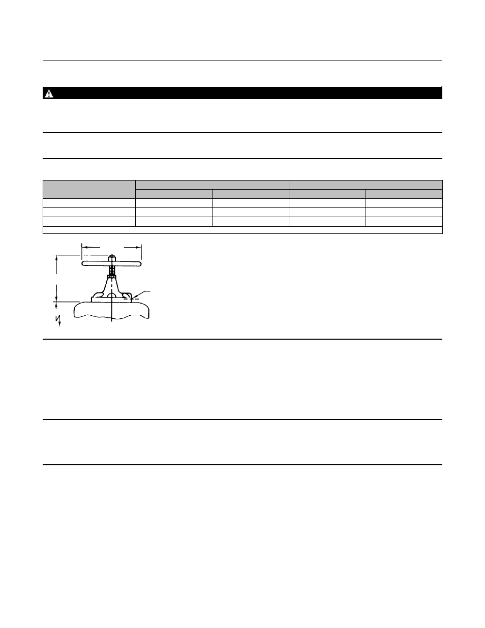
Figure 3. Top Mounted Handwheel
ACTUATOR SIZE
H
C
J
C
mm
Inch
mm
Inch
40
281
11.06
356
14.00
60
359
14.12
432
17.00
70
(1)
335
13.62
356
14.00
1. Size 70 available in 1052 only.
TOP-MOUNTED HANDWHEEL
19A1465-B
1/4 NPT
H
C
J
C
(DIA)
E
Actuator Mounting
Use the following steps to connect the actuator to a valve body or other equipment. Unless otherwise specified, key
numbers are shown in figures 12 and 13. Mounting dimensions are shown in figures 4, 5, 6, and 7.
Note
For an actuator with an H mounting adaptation and a 22.2 through 38.1 mm (7/8 through 1-1/2 inch) output shaft, find
dimensions and center of gravity information in figures 3, 4, 5, 6, and 9, and approximate weights in table 8. This information is
required for proper fabrication of the user-provided bracket and coupling.
1. For an actuator with an H mounting adaptation, attach an appropriate mounting bracket (not provided) to the
mounting plate (key 22) with the cap screws (key 78). See figures 4, 5, and 6 for mounting dimensions on the
mounting plate. Tighten the cap screws to the bolt torques listed in table 4.
2. Consult figure 10 for available mounting styles and positions. The actuator is normally positioned vertically with the
valve body or other equipment in a horizontal pipeline.