Instruction manual – Emerson Process Management 1051 User Manual
Page 6
Instruction Manual
D100320X012
1051 and 1052 H & J Actuators
October 2012
6
Note
If the milled flats or the coupling on the end of the actuator output shaft (key 87) are oriented such that the output shaft cannot
accommodate the operated equipment shaft, refer to the Changing Positions portion of the Changing Actuator Mounting section.
This procedure describes how the output shaft can be repositioned to accommodate the operated equipment shaft.
3. If using an actuator with a J mounting adaptation, note that the valve shaft coupling (key 90) is furnished with two
keyways lettered A and B as shown in figure 8 and 12 (letters C and D on the coupling are not used and can be
disregarded). Align the appropriate keyway with the keyway in the operated equipment shaft. If using a Fisher
butterfly valve, align the appropriate keyway on the coupling with the valve shaft keyway indicated in table 9. Then
install the woodruff key (key 91) in the shaft keyseat, and slide the coupling onto the shaft. It is helpful to apply a
light coat of grease to the inside of the coupling before sliding it onto the shaft.
4. For an actuator with an H mounting adaptation, slide the actuator (with the user-provided mounting bracket
attached) into the user-provided coupling on the operated shaft. Then, secure the actuator to the operated
equipment in the desired mounting position with the appropriate fasteners, such as mounting cap screws. See
figures 4, 5 and 6 for output shaft dimensions.
5. For an actuator with a J mounting adaptation, secure the mounting bracket (key 22) to the valve body with the cap
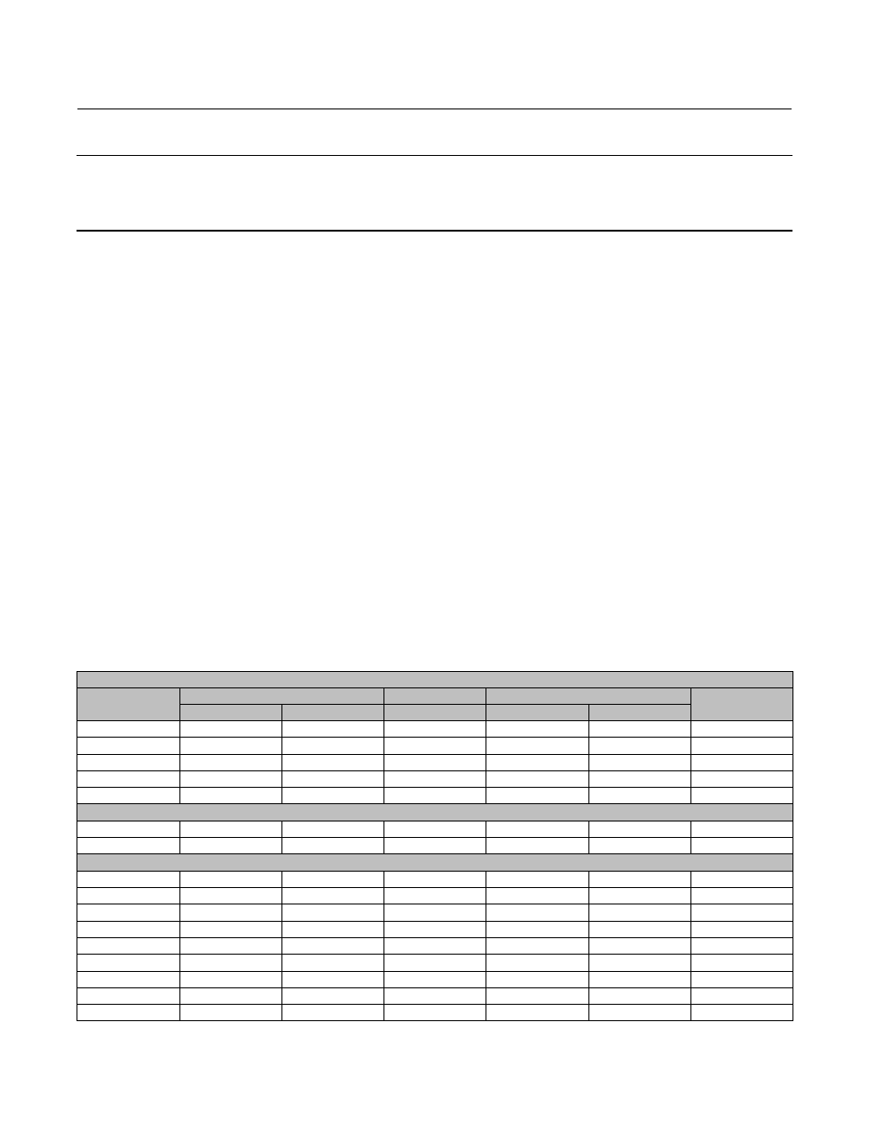
screws (key 78, not shown). Tighten the cap screws to the bolt torques in table 4. For 31.8 and 38.1 mm (1-1/4 and
1-1/2 inch) valve shafts, also place the two spacers (key 92, not shown) between the mounting bracket and valve
body during this step.
6. For an actuator with a J mounting adaptation and a 50.8 mm (2-inch) output shaft (key 87, figure 14), note that the
valve shaft coupling (key 90, figure 14) is furnished with two keyways lettered A and B as shown in figure 8 (letters C
and D on the coupling are not used and can be disregarded). Align the appropriate keyway with the keyway in the
operated equipment shaft. Then, install the woodruff key (key 91, not shown in figure 14) in the shaft keyseat, and
slide the coupling onto the shaft using the appropriate coupling keyway (see table 9 and figure 8). It is helpful to
apply a light coat of grease to the inside of the coupling before sliding it onto the shaft. Secure the actuator
(user-provided mounting bracket) to the operated equipment in the desired mounting position with the
appropriate fasteners, such as mounting cap screws.
7. Follow the instructions given in the Turnbuckle Adjustment section before proceeding to the Loading Connection
portion of this section.
Table 4. Key 78 Cap Screw Torque Values
STYLE H MOUNTING
Actuator Size
Valve Shaft Diameter
Bolt Size
Bolt Torque
Key 78
Part Number
mm
Inch
Inch
N•m
lbf•ft
40
22.2
7/8
5/16
22.6
16.7
1C5958X0042
40
28.6
1-1/8
3/8
39
29
1A353124052
60
28.6
1-1/8
3/8
39
29
1A353124052
40
38.1
1-1/2
1/2
92
68
1A582324052
60, 70
38.1
1-1/2
1/2
92
68
1A582324052
STYLE J MOUNTING - FLAT PLATE MOUNTING
60, 70
44.5
1-3/4
1/2
92
68
1A582324052
60, 70
50.8
2
1/2
92
68
1A582324052
STYLE J MOUNTING - FISHER 7600, 9100, 9500 WITH KEYED SHAFT
40
9.5
3/8
3/8
39
29
1A341824052
40
12.7
1/2
3/8
39
29
1A341824052
40
15.9
5/8
3/8
39
29
1A341824052
40
19.1
3/4
3/8
39
29
1A341824052
60
19.1
3/4
3/8
39
29
1A341824052
40
25.4
1
3/8
39
29
1A341824052
60
25.4
1
3/8
39
29
1A341824052
60, 70
31.8
1-1/4
5/8
163
120
1P1477X0012
60, 70
38.1
1-1/2
5/8
163
120
1P1477X0012