Cable connection to lc fiber-optic connectors -13, Figure 4‐11 – Enterasys Networks 7S4280-19-SYS User Manual
Page 53
Connecting to the Network
Enterasys NAC Controller Hardware Installation Guide 4-13
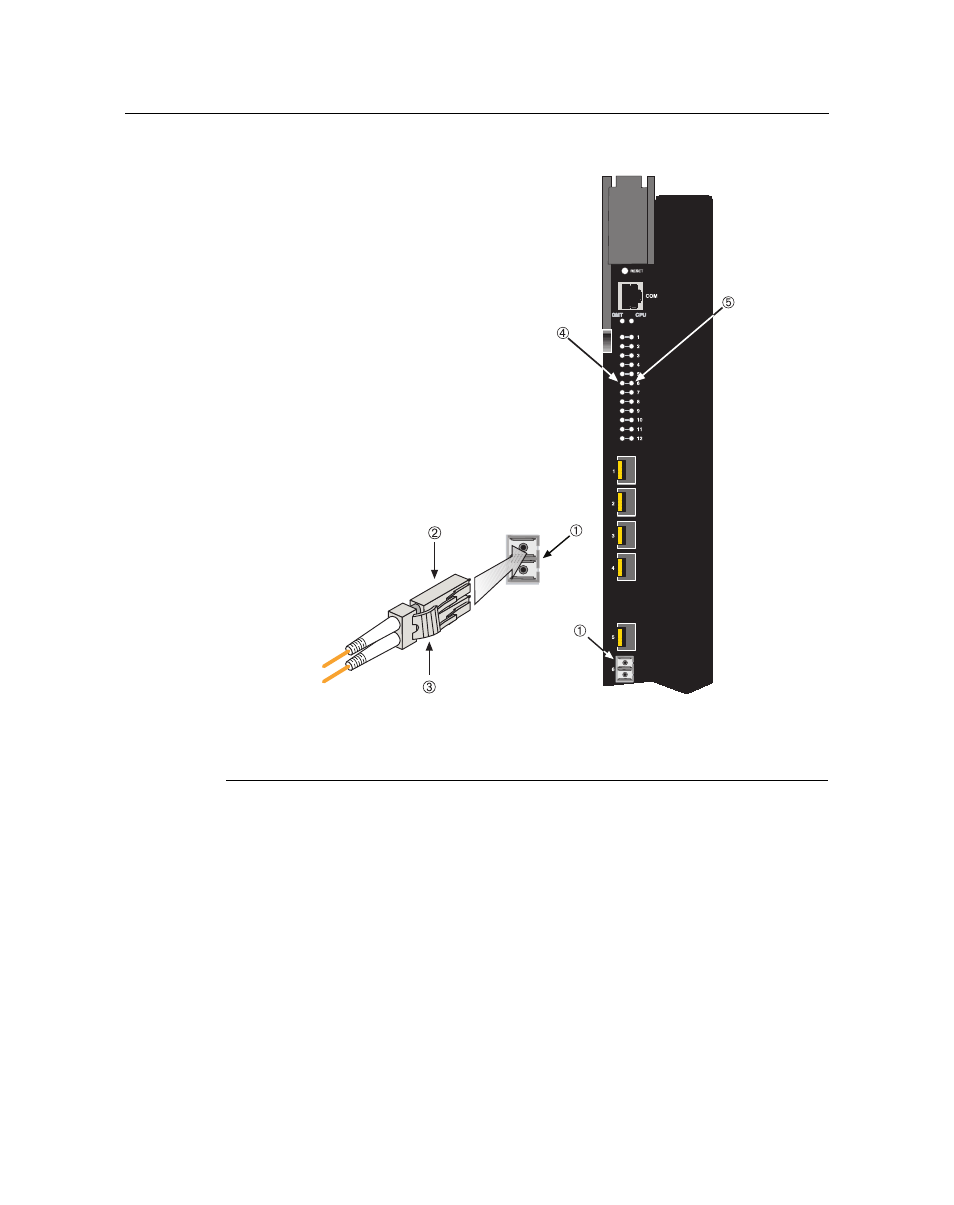
Figure 4-11 Cable Connection to LC Fiber-Optic Connectors
3.
Verify that a link exists by checking that the port RX LED is on (flashing amber, blinking
green, or solid green). If the RX LED is off, perform the following steps until it is on:
a.
Verify that the device at the other end of the segment is ON and connected to the segment.
b. If there are separate fiber‐optic connections on the other device, check the crossover of the
cables. Swap the cable connections if necessary.
c.
Check that the fiber‐optic connection meets the dB loss and cable specifications outlined
in the Cabling Guide for multimode fiber‐optic cabling. To obtain this document, refer to
“
Related Documents” on page xvi
.
If a link has not been established, refer to
for LED troubleshooting details. If a
problem persists, refer to “
Enterasys Networks for support.
4.
Repeat steps 1 through 3, above, until all connections have been made.
1 Installed Mini-GBIC LC connector
4 Receive LED (RX)
2 LC cable connector
5 Transmit LED (TX)
3 Release tab