Memory Locations and Replacement Procedures
B-6 Mode Switch Bank Settings and Optional Installations
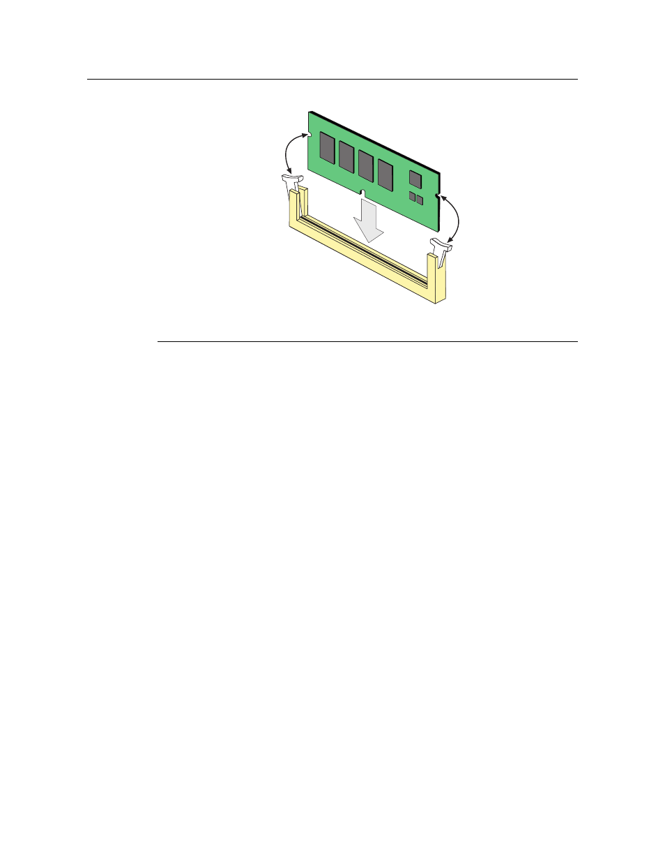
Figure B-6 Installing the DRAM SIMM
1 DRAM SIMM Connector arms
3 Connector contacts
2 DRAM SIMM
4 DRAM SIMM alignment notches (2)
Б
В
Г
А