7 - gpio setup and connections, Ear panel. see, Section 7 – Ashly FX60.2 Multipurpose Installation Network Amplifier with DSP (1 RU, 1/2 Rack) User Manual
Page 14: Gpio setup and connection, Fx amplifier • operating manual, Configuration
14
FX Amplifier • Operating Manual
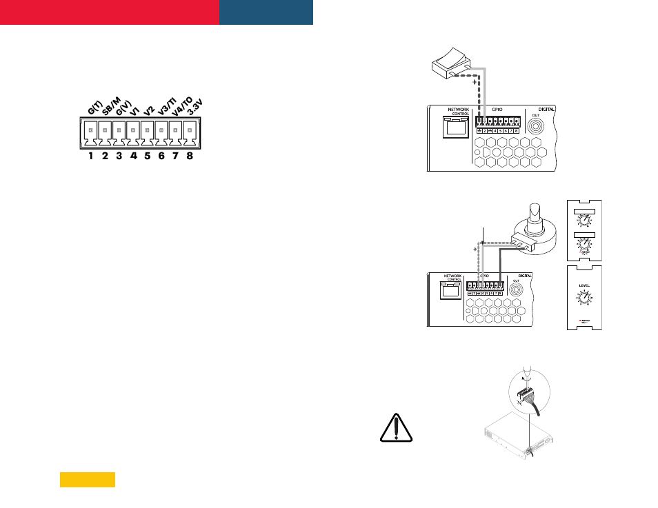
7. GPIO Setup and Connection
FX amplifiers offer a GPIO Euroblock socket that
enables remote control of volume, standby,
mute and trigger functions.
(Diagram 7.3)
Some GPIO pins have multiple functions
depending on their configuration. Each pin
function is described below, as well as in the
Settings>GPIO configuration menu.
•
Pin 1,
Soft Ground,
use only for 12V trigger
and standby/mute input reference.
•
Pin 2,
Standby or Mute
(Diagram 7.1)
Off, Pin 2 has no functionality (default)
Standby (NO) Amplifier will enter Standby
when Pin 2 is connected to Pin 1 GND.
Standby (NC) Amplifier will enter
Standby when Pin 2 is unconnected (floating).
Mute (NO) All amplifier outputs are
muted when Pin 2 is connected to Pin 1 GND.
Mute (NC) All amplifier outputs are
muted when Pin 2 is unconnected (floating).
•
Pin 3, Ground
, use only as ground reference
for GPIO Volume Control and Trigger Out.
•
Pin 4,
GPIO Volume Control
(Diagram 7.2)
Off, Pin 4 has no functionality (default)
GPIO Volume Control, When selected, Pin
4 is available for remote volume control input
assignment in Zone>GPIO Volume Control menu.
•
Pin 5,
GPIO Volume Control
(Diagram 7.2)
Off, Pin 5 has no functionality (default)
GPIO Volume Control, When selected, Pin
5 is available for remote volume control input
assignment in Zone>GPIO Volume Control menu.
•
Pin 6,
Volume Control
or
12V Trigger In
Off, Pin 6 has no functionality (default)
GPIO Volume Control, When selected,
Pin 6 is available for remote volume control
input assignment in Zone>GPIO Volume
Control menu.
(Diagram 7.2)
12V Trigger In, Amplifier will operate when
12V signal is applied to Pin 6, and will enter
Standby when no voltage is applied. Note: This
requires Trigger-Mode to be selected in the
Settings>Power Management menu
•
Pin7,
Volume Control
or
12V Trigger Out
Off, Pin 7 has no functionality.
GPIO Volume Control, When selected,
Pin 7 is available for remote volume control
input assignment in Zone>GPIO Volume
Control menu.
(Diagram 7.2)
12V Trigger Out, When selected, Pin
7 provides 12V for use with Trigger Input
function on Pin 6. (default)
•
Pin 8
, 3.3V power,
use for GPIO volume
controls. Note: GPIO Pin 8 has an output
impedance of 1kΩ. Connected devices must
be able to sink 3.3mA.
Note: The GPIO connector must not
be used for any unintended purpose.
Amplifier damage may result from
incorrect use of GPIO pins. Shielded
cable must be used when connecting standby
switches and potentiometers via GPIO pins.
Diagram 7.1:
GPIO Connections for remote
standby/mute switch
Diagram 7.2:
GPIO Potentiometer connections
for remote volume control. Use Ashly WR-1 or
WR-1.1 wall remote or equivalent circuit.
Diagram 7.3:
GPIO connections
Connect Wiper to Pin 4, 5, 6, or7
Potentiometer (>10k Ω)
Gr
ound
+3.3V
Switch open or closed
toggles Standby or Mute
depending on options
selected in the GPIO
Settings Menu
Gr
ound
Standb
y/M
ut
e
5 mm
Configuration