Dnp digital input data – ProSoft Technology MVI46-DNP User Manual
Page 67
Reference MVI46-DNP
♦ SLC Platform
Master/Slave Communication Module
ProSoft Technology, Inc.
Page 67 of 143
August 23, 2007
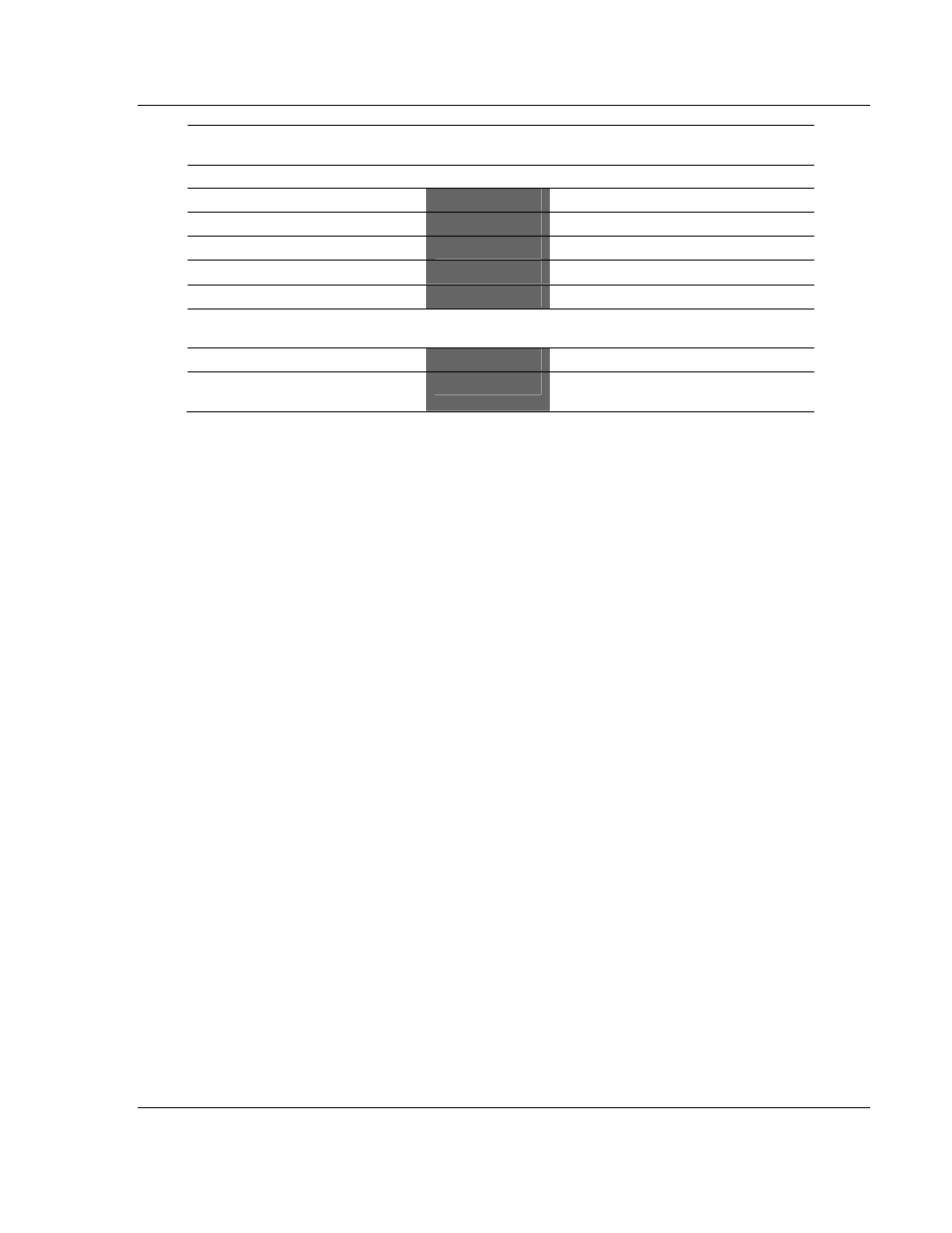
SLC Files
M1: File Data
DNP Memory
DNP Master Device
IED Memory
DNP Slave Device
Digital Input File
←
←
Digital Input Data
Analog Input File
←
←
Analog Input Data
Counter Data File
←
←
Counter Data
Digital Output File
→
→
Digital Output Data
Analog Output File
→
→
Analog Output Data
Floating-Point
Data
DNP Master Device
Float Input
→
→
Floating-Point Input Data
Float Output
←
←
Floating-Point Output
Data
It is recommended to associate each individual data type with a separate file in
the SLC. This permits easier management of the ladder logic and expansion of
the system.
DNP Digital Input Data
This data type stores the binary value of 1 or 0. The size of this data area is
determined from the configuration parameter Number of Binary Input Points. The
data area is partitioned into two separate areas. The first is the DNP binary input
data acquired from the SLC, and the second is the binary input data from IED
units on the DNP master port. The configuration parameter, Number of Binary
Input Points for SLC, determines the size of the SLC's data area. The remaining
portion is defined as the IED binary input data area.
SLC data are transferred to the module from the SLC using the COP command
in the ladder logic. Therefore, these data are read-only for the module and the
DNP master unit communicating with the module. When the module receives a
new block of this data from the SLC, it compares the new values to those
currently in the database. If there is a change in any of the data, the module
generates an event message for the points that change.
Data from IED units can also be placed in the DNP binary input data area.
Commands in the command list must specify the DNP database address (point
number) where the data will be placed.