ProSoft Technology MVI56-GEC User Manual
Page 72
Reference
MVI56-GEC ♦ ControlLogix Platform
User Manual
Generic ASCII Ethernet Communication Module
Page 72 of 108
ProSoft Technology, Inc.
October 8, 2010
Backplane Data Transfer
The MVI56-GEC module communicates directly over the ControlLogix
backplane. Data travels between the module and the ControlLogix processor
across the backplane using the module's input and output images. The update
frequency of the data is determined by the user-defined scan rate for the module,
and the communication load on the module. Typical updates are in the range of 1
to 10 milliseconds.
Data received by the module's clients and servers is placed in the module's
Database. This data is read and then processed by the ladder logic in the
ControlLogix processor through the Input Image (Local Input connection). The
input image parameter in RSLogix 5000 for the module is set to 250 registers
(500 bytes).
The processor writes data through the Output Image (Local Output connection)
for transfer into the module's Database. The module's program extracts the data
from the module's Database and transmits the data out to the Ethernet network.
Each message is directed to a client or server that is connected to a remote host.
The Output image parameter in RSLogix for the module is set to 248 registers
(496 bytes). This large I/O area permits fast throughput of data between the
module and the processor.
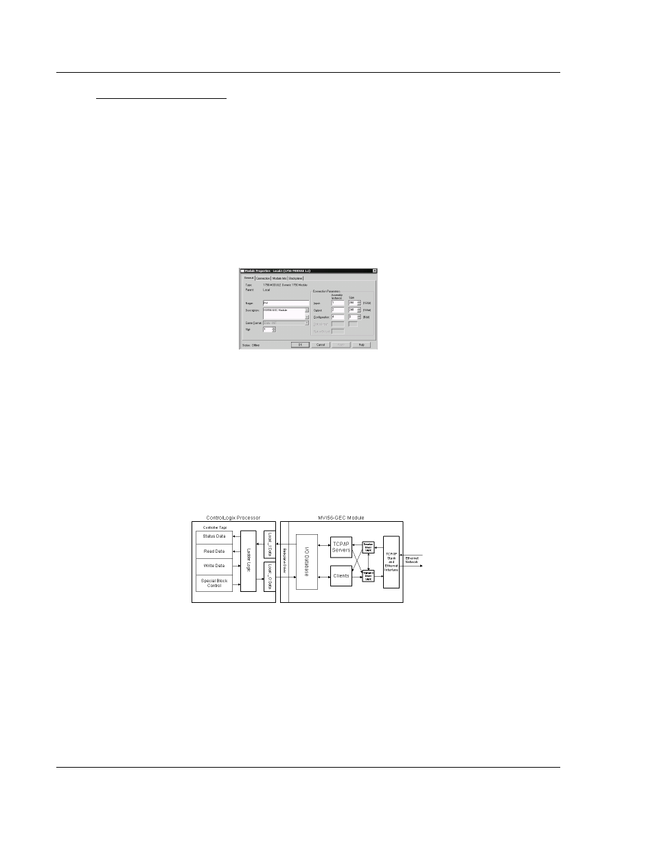
The following illustration shows the data transfer method used to move data
between the ControlLogix processor, the MVI56-GEC module, and the Ethernet
network.
All data transferred between the module and the processor over the backplane is
through the input and output images. Ladder logic must be written in the
ControlLogix processor to interface the input and output image data defined in
the controller tags.
You must configure the module properly for accurate reception of data through its
ports, and you must program the ladder logic to interpret the data from the
module and send the correct response to the module.
Use the sample ladder logic program on the CD-ROM to establish data transfer
between the module and the processor.