ProSoft Technology MVI69-DFNT User Manual
Page 85
MVI69-DFNT ♦ CompactLogix or MicroLogix Platform
Reference
EtherNet/IP Client/Server Communication Module
User Manual
ProSoft Technology, Inc.
Page 85 of 167
May 14, 2014
During normal program operation, the module sequentially sends read blocks
and requests write blocks. For example, if the application uses three read and
two write blocks, the sequence will be as follows:
R0W1
R1W2
R2W1
R3W2
R0W1
R1W2
R2W1
R3W2
Notice that ReadBlock 0, the read block that contains status information, appears
at the start of each read block cycle. This means status information in the
controller tags will update only after all other read data blocks have been
updated.
The sequence will continue unless interrupted by special function write block
numbers sent by the controller or by a command request from a node on the
DFNT network or operator control through the module’s Configuration/Debug
port. For more information, see Special Function Blocks.
Here are some additional examples of alternative backplane communication
setups.
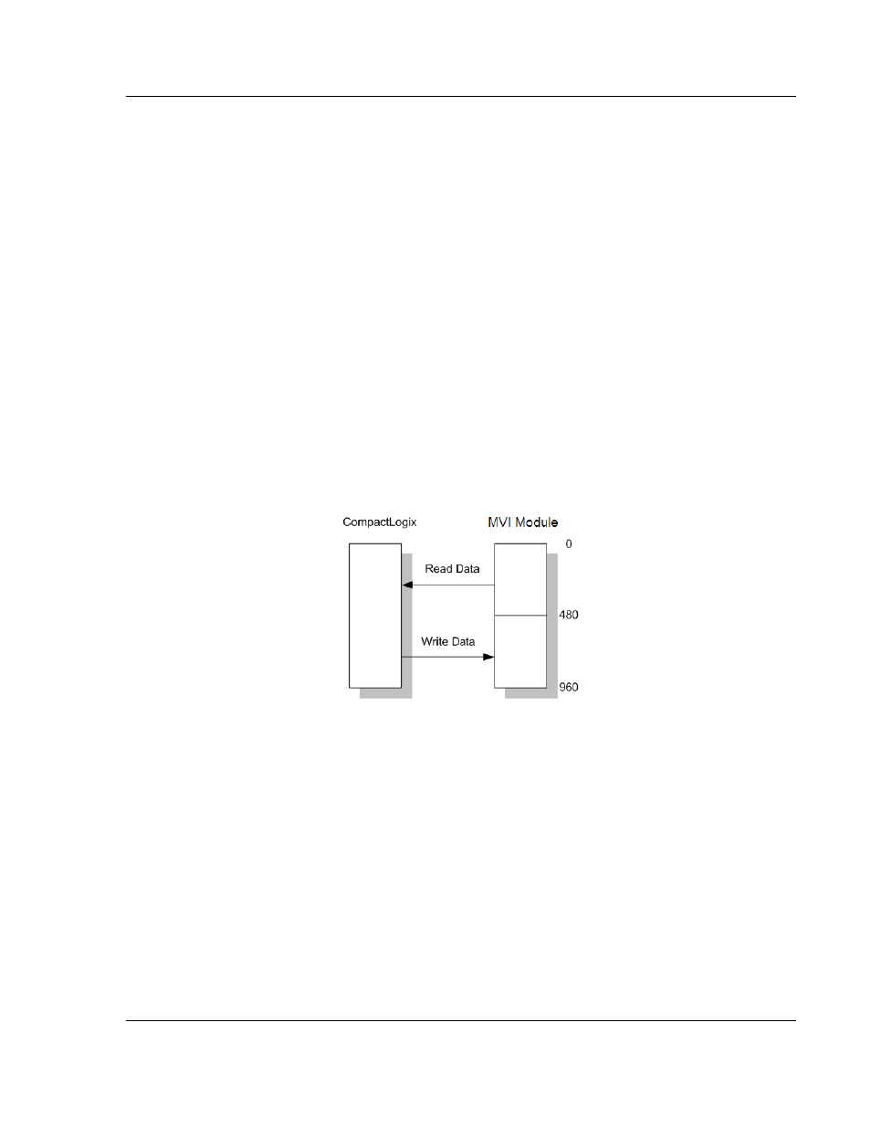
Assume that the backplane parameters are configured as follows:
Read Register Start: 0
Read Register Count: 480
Write Register Start: 480
Write Register Count: 480
The module data areas would be allocated as follows:
Database address 0 to 479 will be continuously transferred from the module to
the processor. Database address 480 to 959 will be continuously transferred
from the processor to the module.