Normal data transfer – ProSoft Technology MVI69E-MBS User Manual
Page 71
MVI69E-MBS ♦ CompactLogix Platform
MVI69E-MBS Backplane Data Exchange
Communication Module
User Manual
ProSoft Technology, Inc.
Page 71 of 162
January 6, 2014
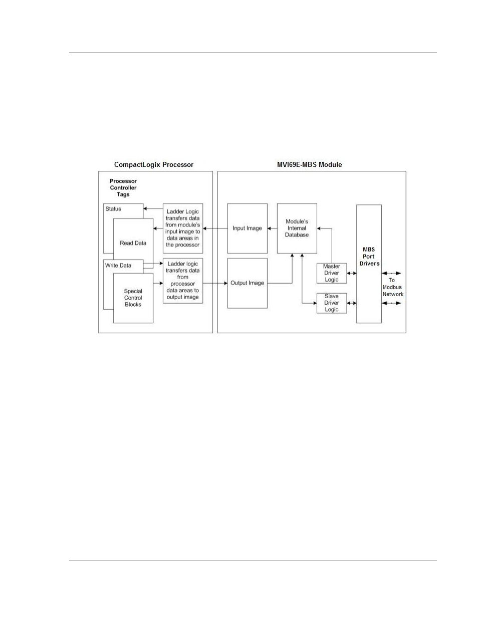
The processor inserts data to the module's output image to transfer to the
module. The module's program extracts the data and places it in the module's
internal database. The output image for the module may be set to 61, 121, or 241
words depending on the block transfer size parameter set in the configuration
file.
The following illustration shows the data transfer method used to move data
between the CompactLogix processor, the MVI69E-MBS module and the
Modbus Network.
All data transferred between the module and the processor over the backplane is
through the input and output images. Ladder logic in the CompactLogix
processor interfaces the input and output image data with data defined in the
Controller Tags. All data used by the module is stored in its internal database.
This database is defined as virtual MBS data tables with addresses from 0 to the
maximum number of points for each data type.
4.3
Normal Data Transfer
Normal data transfer includes the paging of the user data found in the module’s
internal database (Registers 0 to 9999) and the status data. These data are
transferred through read (input image) and write (output image) blocks. The
following topics describe the structure and function of each block.