Modbus port x – ProSoft Technology MVI69E-MBS User Manual
Page 54
MVI69E-MBS Configuration
MVI69E-MBS ♦ CompactLogix Platform
User Manual
Communication Module
Page 54 of 162
ProSoft Technology, Inc.
January 6, 2014
Yes, the data is initialized with Read Register Data values
from the processor. Using this option requires associated
ladder logic to pass the data from the processor to the
module.
Block Transfer Size
60, 120 or
240
Specifies the number of words in each block transferred
between the module and processor.
Slot Number
1 to x
Specifies the slot in the CompactLogix rack for the
module.
Important: The sum of the Read Register Count and Write Register Count cannot exceed 10,000
total registers. Furthermore, neither the Read Data nor the Write Data area may extend above
module register 9999. The Read Data and Write Data areas must not overlap.
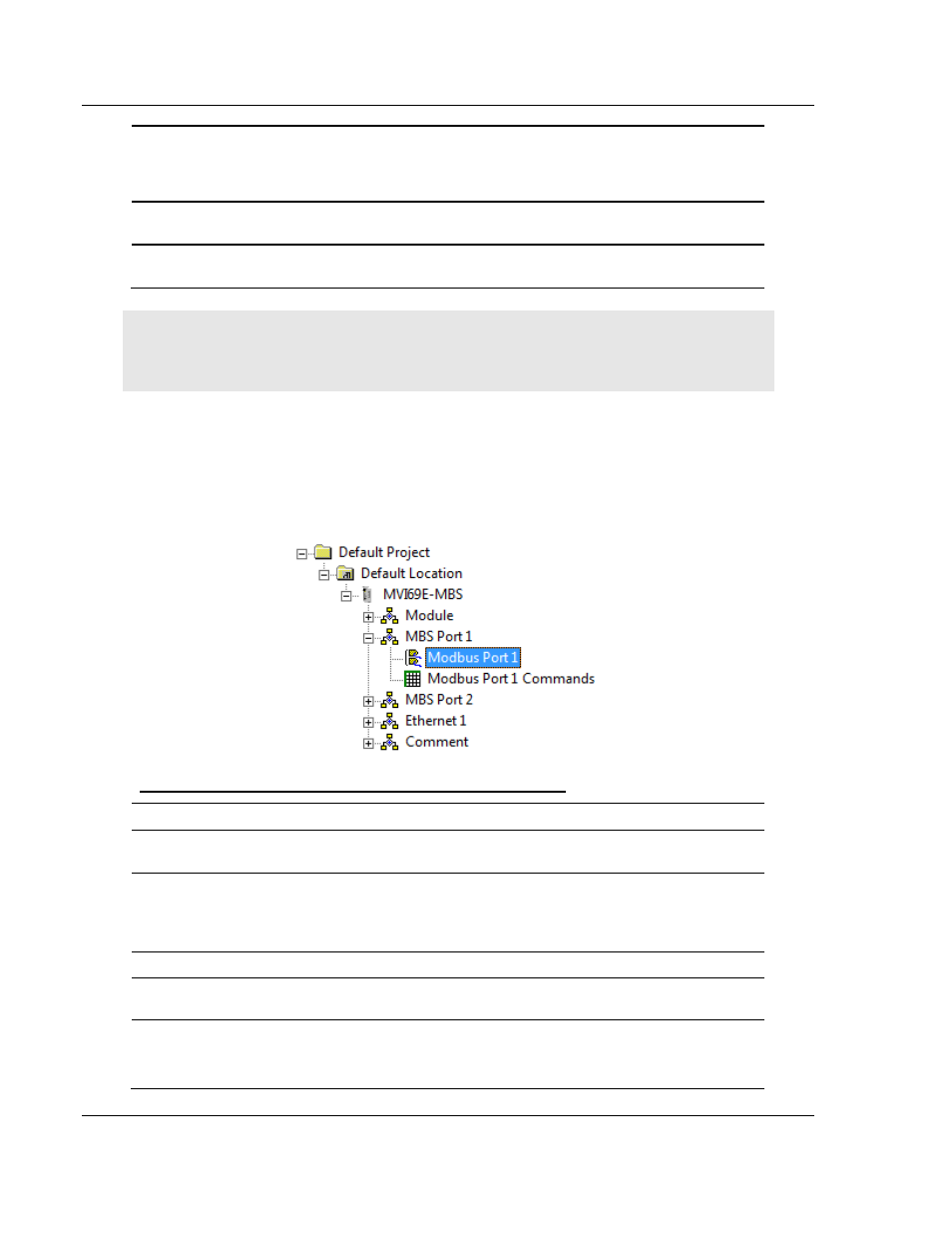
3.2.2 Modbus Port x
The information in this section applies to both Port 1 and Port 2.
In PCB’s tree view, double-click the M
ODBUS
P
ORT X
icon.
Configuration Parameters Common to Master and Slave
Parameter
Value
Description
Start Active
Yes or No
Specifies whether or not the port and commands are active
upon module boot-up.
Type
Master, Slave,
or Slave with
Pass-Through
This parameter specifies which device type the port emulates.
Refer to Slave on page 76 for more information on Slave
Pass-Through options.
Protocol
RTU or ASCII
Specifies the Modbus protocol to be used on the port.
Baud Rate
Multiple
options
Specifies the baud rate to be used on the port.
Parity
None
Odd
Even
Specifies the type of parity error checking to use. All devices
communicating through this port must use the same parity
setting.