Figure2.1 hardware connections for the lsi21040, Hardware connections for the lsi21040, Figure 2.1 – Avago Technologies LSI21040 User Manual
Page 22
3.75 pc
10.25 pc
11.25 pc
38.25 pc
4.333 pc
48.583 pc
52.5 pc
34.5 pc
44.25 pc
2-4
Installing the LSI21040
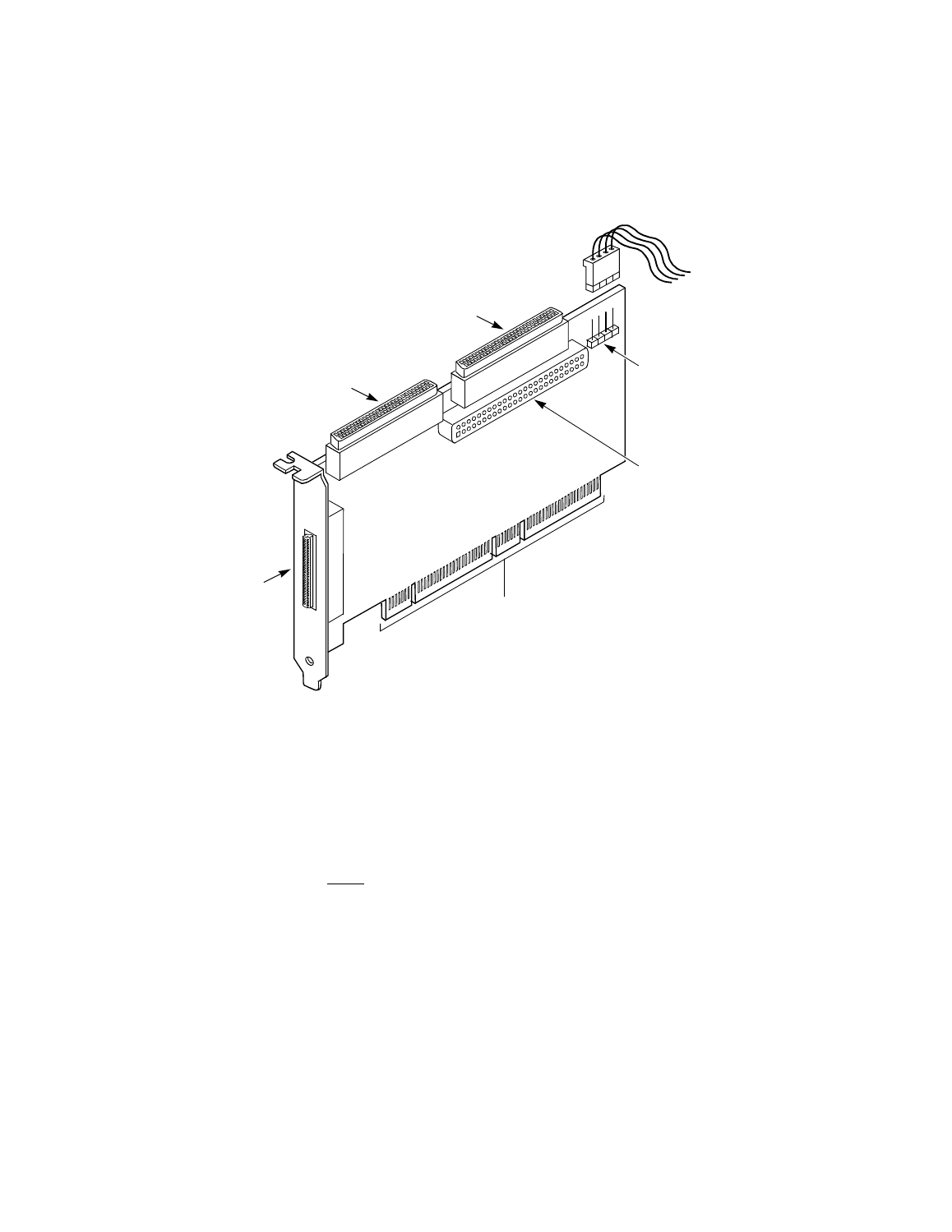
Figure 2.1
Hardware Connections for the LSI21040
Step 7.
Carefully insert edge connector J1 (see
) of the host
adapter into the PCI slot.
Make sure the edge connector is properly aligned before
pressing the board into place as shown in
. The
bracket around connector J3 should fit where you removed the
blank panel.
Note:
You may notice that the components on a PCI host adapter
face the opposite way from non-PCI adapter boards you
have in your system. This orientation is correct. The board
is keyed and will only go in one way.
Channel B 68-Pin
Internal High
Density SCSI
Connector J2
Channel A 68-Pin
Internal High
Density SCSI
Connector J4
68-Pin External
High Density SCSI
Connector J3
LSI21040 PCI Bus
Edge Connector J1
Channel A and B
Busy LED
Channel B 50-Pin
Low Density SCSI
Connector J5
Connector J6
- MGA-725M4 (4 pages)
- MGA-71543 (4 pages)
- MGA-71543 (3 pages)
- MGA-82563 (6 pages)
- 3ware SAS 9750-8i (48 pages)
- 3ware 9690SA-8I (Channel) (138 pages)
- 3ware 9690SA-8I (Channel) (380 pages)
- 3ware SAS 9750-8i (29 pages)
- 3ware 9550SXU-8LP (Channel) (149 pages)
- 3ware 9550SXU-8LP (Channel) (40 pages)
- 3ware 9650SE-8LPML (Channel) (45 pages)
- 3ware 9690SA-8I (Channel) (27 pages)
- 3ware 9690SA-8I (Channel) (361 pages)
- 6160 SAS Switch (2 pages)
- MegaRAID SAS 9361-8i (13 pages)
- MegaRAID SAS 9266-8i (12 pages)
- MegaRAID SAS 9380-8e (43 pages)
- Cache Protection for RAID Controller Cards (139 pages)
- Cache Protection for RAID Controller Cards (13 pages)
- MegaRAID SAS 9271-8iCC (13 pages)
- MegaRAID SAS 9285-8ecv (92 pages)
- MegaRAID SAS 9266-8i (20 pages)
- MegaRAID SAS 9271-8iCC (26 pages)
- MegaRAID SafeStore Software (502 pages)
- MegaRAID SAS 9285-8ecv (80 pages)
- MegaRAID SAS 0260CV-4i (64 pages)
- MegaRAID SAS 0260CV-4i (49 pages)
- MegaRAID SAS 9271-8i (8 pages)
- MegaRAID SAS 0260CV-4i (72 pages)
- MegaRAID SAS 9361-8i (7 pages)
- MegaRAID SAS 9341-8i (8 pages)
- MegaRAID SAS 9380-4i4e (7 pages)
- MegaRAID SAS 9380-8e (7 pages)
- MegaRAID SAS 9240-8i (4 pages)
- MegaRAID SAS 0260CV-4i (28 pages)
- MegaRAID SAS 9260-16i (12 pages)
- MegaRAID SAS 9280-24i4e (14 pages)
- MegaRAID SAS 9280-24i4e (16 pages)
- MegaRAID SAS 9260-8i (4 pages)
- MegaRAID SafeStore Software (8 pages)
- MegaRAID SAS 9280-8e (22 pages)
- MegaRAID SAS 9261-8i (4 pages)
- MegaRAID SAS 9285-8e (12 pages)
- MegaRAID SAS 9280-16i4e (12 pages)
- MegaRAID SAS 9280-4i4e (4 pages)