Avago Technologies MegaRAID SAS 8204ELP User Manual
Page 49
MegaRAID 1078-based SAS RAID Controller Family
3-5
Copyright © 2007 by LSI Corporation. All rights reserved.
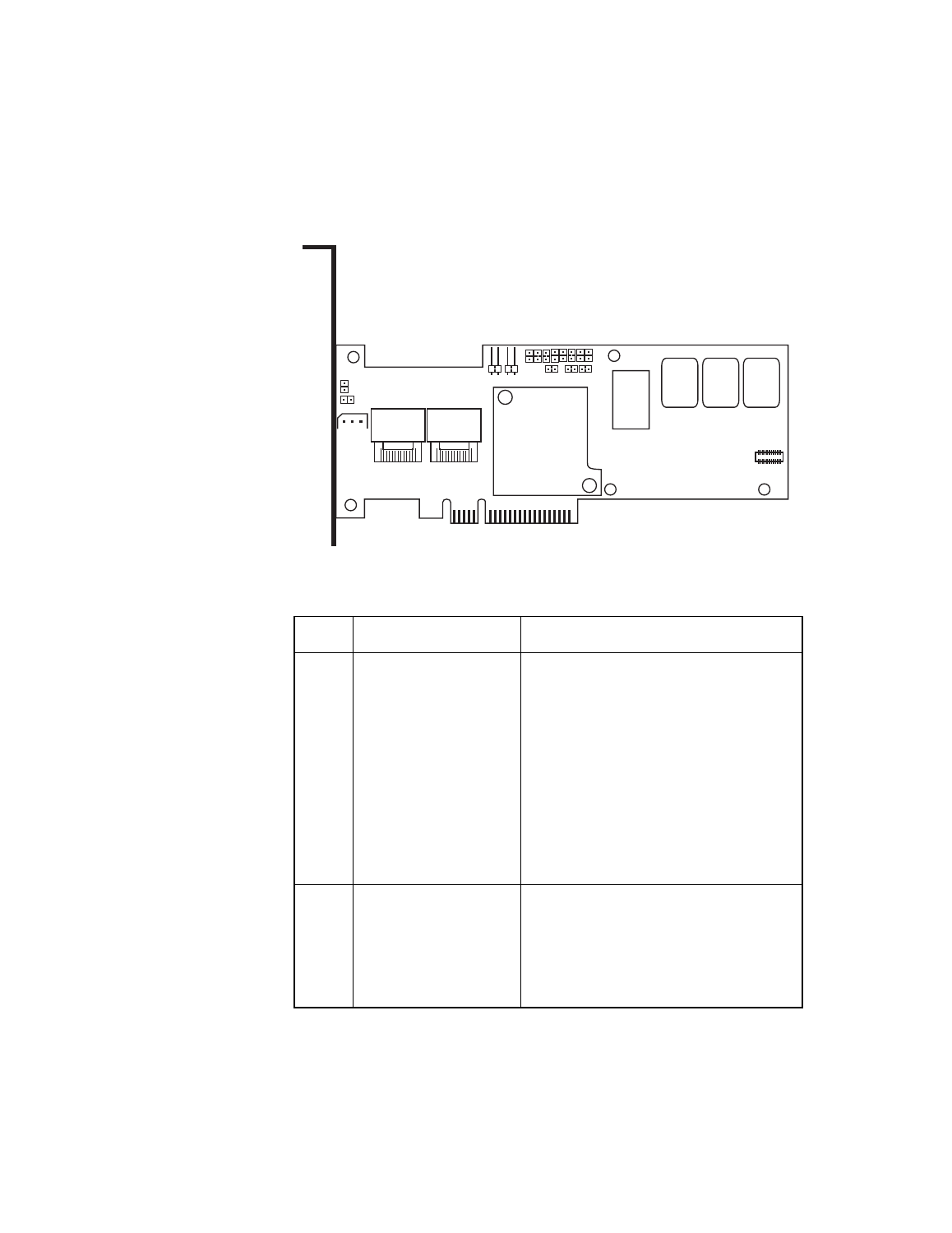
Figure 3.2
Card Layout for the MegaRAID SAS 8708EM2 RAID
Controller
Table 3.2
SAS 8708EM2 RAID Controller – Jumpers and
Connectors
Jumper Type
Description
J1
Individual Fault LED
header for eight ports
16-pin connector.
Indicates hard drive faults. There is one LED
per port. When lit, each LED indicates the
corresponding hard drive has failed or is in
the Unconfigured-Bad state. Refer to the
MegaRAID SAS Software User’s Guide for
more information about drive states.
The LEDs function in a direct-attach
configuration (there are no SAS expanders).
Direct attach is defined as a maximum of
one hard drive connected directly to each
port.
J2
Cache Write Pending
LED
2-pin connector.
The connector for the enclosure LED. It
provides a signal that indicates when the
on-board cache contains data and a write
from the cache to the hard drives is
pending. Optional.
85020-00
J7
J6
Port
3-0
Port
7-4
J8
J12
J9
J5
J1
J10
J4
J3
J2
- MegaRAID SAS 8204ELP (Channel) MegaRAID SAS 8204XLP MegaRAID SAS 8204XLP (Channel) MegaRAID SAS 8208ELP MegaRAID SAS 8208ELP (Channel) MegaRAID SAS 8208XLP MegaRAID SAS 8208XLP (Channel) MegaRAID SAS 8300XLP MegaRAID SAS 8308ELP MegaRAID SAS 8344ELP MegaRAID SAS 84016E MegaRAID SAS 84016E (Channel) MegaRAID SAS 8408E MegaRAID SAS 8480E MegaRAID SAS 8704ELP MegaRAID SAS 8704ELP (Channel) MegaRAID SAS 8704EM2 MegaRAID SAS 8704EM2 (Channel) MegaRAID SAS 8708ELP MegaRAID SAS 8708ELP (Channel) MegaRAID SAS 8708EM2 MegaRAID SAS 8708EM2 (Channel) MegaRAID SAS 8880EM2 MegaRAID SAS 8880EM2 (Channel) MegaRAID SAS 8888ELP MegaRAID SAS 8888ELP (Channel) MegaRAID SAS 0260CV-4i MegaRAID SAS 0260CV-8i