4 power loss circuit, Power loss circuit -2 – KEPCO MAT 1/3 Rack User Manual
Page 33
3-2
MAT1/3 RACK/ 112404
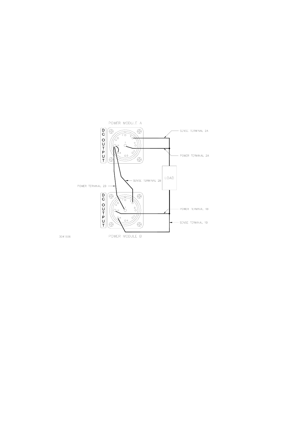
FIGURE 3-1. TWO MAT 1/3 RACK POWER MODULES CONNECTED IN SERIES
VIA THEIR OUTPUT CONNECTOR
3.4
POWER LOSS CIRCUIT
An Automatic Shutdown option is available when a Power Loss is detected. Dependent on the
setting of jumper J5 on the A2 Sense and Polarity Relay Board, the Power Module will shutdown
automatically or remain in operation (see Figure 3-2). If the jumper is in place the AC Input
Power circuit breaker will trip; if the jumper is removed the circuit breaker will not trip. The MAT
Power Module is supplied with the jumper installed. To remove the jumper see Section 6 for
PCB access, and Figure 3-2.
3.5
INTRODUCTION TO CONTROLLING THE MAT POWER MODULE OUTPUT
The MAT family of Power Modules communicates remotely with a controller via the Control Bus.
Each MAT Power Module has a specific address on the bus. The address (from 1 to 30) is
selected by the switches on the side of the unit (see FIG. 3-2 and Table 3-1). This address is set
at Kepco to 3.