5 cooling, 6 installation, Cooling -6 – KEPCO MAT 1/3 Rack User Manual
Page 23: Installation -6
2-6
MAT 1/3 RACK/ 112404
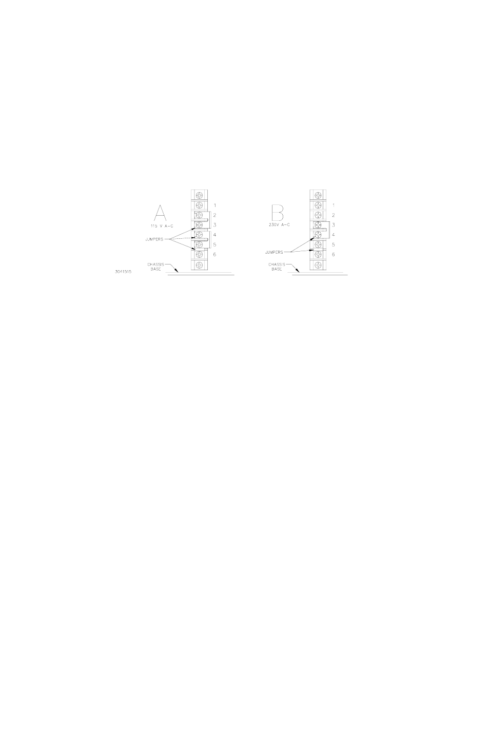
FIGURE 2-3. MAT MODULE BARRIER STRIP WITH JUMPERS FOR 115 OR 230 VA-C
2.5
COOLING
The power transistors and rectifiers in the MAT Power Module are maintained within their oper-
ating temperature range by means of special heat sink assemblies, cooled by an internal fan.
SIDE PANEL OPENINGS AND THE TOP OF THE CASE MUST BE KEPT CLEAR FROM
OBSTRUCTIONS TO ENSURE PROPER AIR CIRCULATION. If the MAT Power Module is
rack mounted, or installed in confined spaces, care must be taken that the ambient temperature
(the temperature immediately surrounding the Power Module) does not rise above the limit
specified in Table 1-1.
2.6
INSTALLATION
If the unit is to be rack mounted install the RA 50 or RA 51 Rack Adapter in the rack per Rack
Adapter instruction manual. Install the MAT 1/3 Rack Power Module in the Rack Adapter hous-
ing and secure with two front panel slotted screws. Refer to Rack Adapter manual for electrical
connections of the rack adapter.
The following steps are recommended for inserting the Power Module into the Rack Adapter.
• Tilt the front of the Power Module slightly lower then the rear, set the two rearmost grom-
mets of the Module on the front lip of the Rack Adapter opening.
• Lift the front of the Module until the bottom is approximately parallel to the bottom of the
Rack Adapter and gently begin slidding in the Module, maintaining support with both
hands as needed to prevent the bottom of the Module from scrapping the lip of the Rack
Adapter.
• Once the Module has been inserted approximately 1 inch, lift the handle upward, raising
the front of the Power Module some 20° up relative to the back bottom edge of the unit
(about an inch over the bottom front lip of the Rack Adapter). Allow the Module to slide
against the bottom inside guides of the Rack Adapter. As this step is being done MAKE
SURE that the top of the Power Module, in particular the white connector on top of the
power module, clears the top edge of the Rack Adapter.
• Continue to lift the unit by the front handle while inserting the Module, until the frontmost
pair of grommets clear the front lip of the Rack Adapter, then allow the Module weight to
be fully supported by the grommets on the bottom of the Module.