Figure 2-2. rear view of the 1/3 rack power module, Table 2-4. rear terminations mat power module, Rear view of the 1/3 rack power module -4 – KEPCO MAT 1/3 Rack User Manual
Page 21: Rear terminations mat power module -4, Ac input/control bus connector pin designations -4
2-4
MAT 1/3 RACK/ 112404
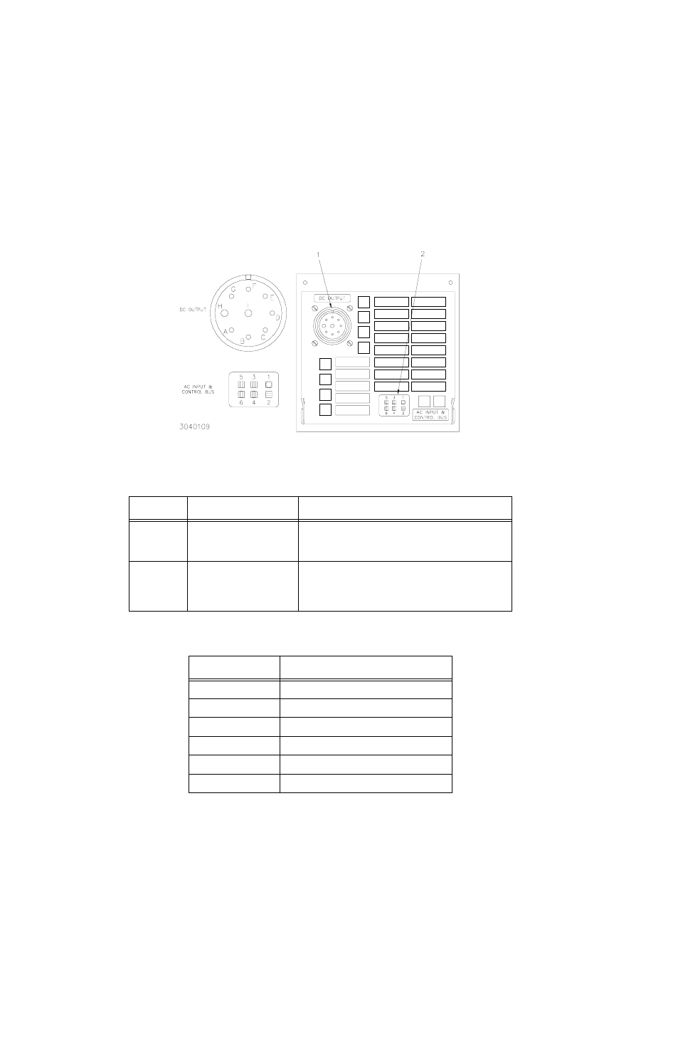
FIGURE 2-2. REAR VIEW OF THE 1/3 RACK POWER MODULE
TABLE 2-4. REAR TERMINATIONS MAT POWER MODULE
ITEM NO.
(See Fig. 2-2)
REAR TERMINATION
FUNCTION
1
DC OUTPUT CONNECTOR
Connects the MAT power module output lines, sensing lines and
ground line to the load (See Table 2-6 for pin designations.) Type
MS3102A16-10P, (mating connector MS3108A16--10S, KEPCO
P/N 143-0331, supplied).
2
AC INPUT POWER/CONTROL
BUS CONNECTOR
Connects MAT power module to a-c input power source and Bitbus
controller via RA 50 or RA 51 rack adapter. Five pins are used for
ac input, two for control bus connections (see Table 2-5). The
power module controller and up to 27 MAT power modules can be
connected (daisy chained) to the control bus (see PAR. 1.2).
TABLE 2-5. AC INPUT/CONTROL BUS CONNECTOR PIN DESIGNATIONS
CONNECTOR PIN
(See Figure 2-2)
FUNCTION
1
SAFETY GROUND
2
AC “H” (HOT)
3
AC “N” (NEUTRAL)
4
NOT USED
5
CONTROL BUS (IEEE 1118 BUS) LINE
6
CONTROL BUS (IEEE 1118 BUS) LINE