4 load connection, local error sensing, Figure 2-5. load connections, local sensing, Load connection, local error sensing -9 – KEPCO MAT 1/3 Rack User Manual
Page 26: Load connections, local sensing -9
MAT 1/3 RACK/ 112404
2-9
A practical model for a voltage stabilized Power Module includes a series inductance represent-
ing dc and low frequency source impedance. Load leads should have minimum voltage drops
(error sensing is discussed below) and minimum inductance (error sensing does not compen-
sate for this). Similarly a model for a current stabilized Power Module includes a parallel capaci-
tor representing the dc and low frequency source impedance.
These considerations are important if:
1) The load is constantly changing value
2) The load is switched "on" and "off"
3) The output of the Power Module is step programmed
4) The load is reactive
5) Dynamic output response of the Power Module is of concern
2.7.4
LOAD CONNECTION, LOCAL ERROR SENSING
The DC OUTPUT connector is located on the back of chassis, and is designated A6-J2 in the
schematic. Table 2-6 and Figure 2-2 provide the function and location of DC OUTPUT connector
pins.
NOTE: The sense terminals MUST be configured for either local sensing (as follows) or
remote sensing (see PAR. 2.7.5) for the MAT Power Module to operate. If left
unconnected the unit will automatically isolate the load and shut down.
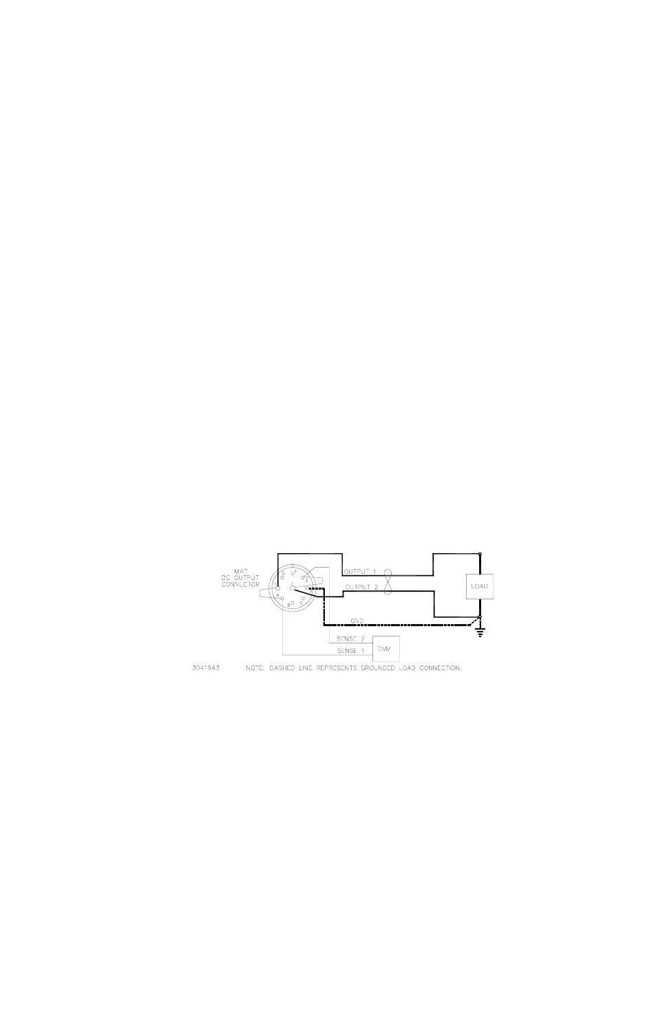
For Local sensing connect Output Terminal 1 to Sense Terminal 1, and Output Terminal 2 to
Sense Terminal 2 at the DC Output connector (see Figure 2-5).
FIGURE 2-5. LOAD CONNECTIONS, LOCAL SENSING