5 load connection with remote error sensing, Figure 2-6. load connections, remote sensing, 8 operating configuration – KEPCO MAT 1/3 Rack User Manual
Page 27: Load connection with remote error sensing -10, Operating configuration -10, Load connections, remote sensing -10
2-10
MAT 1/3 RACK/ 112404
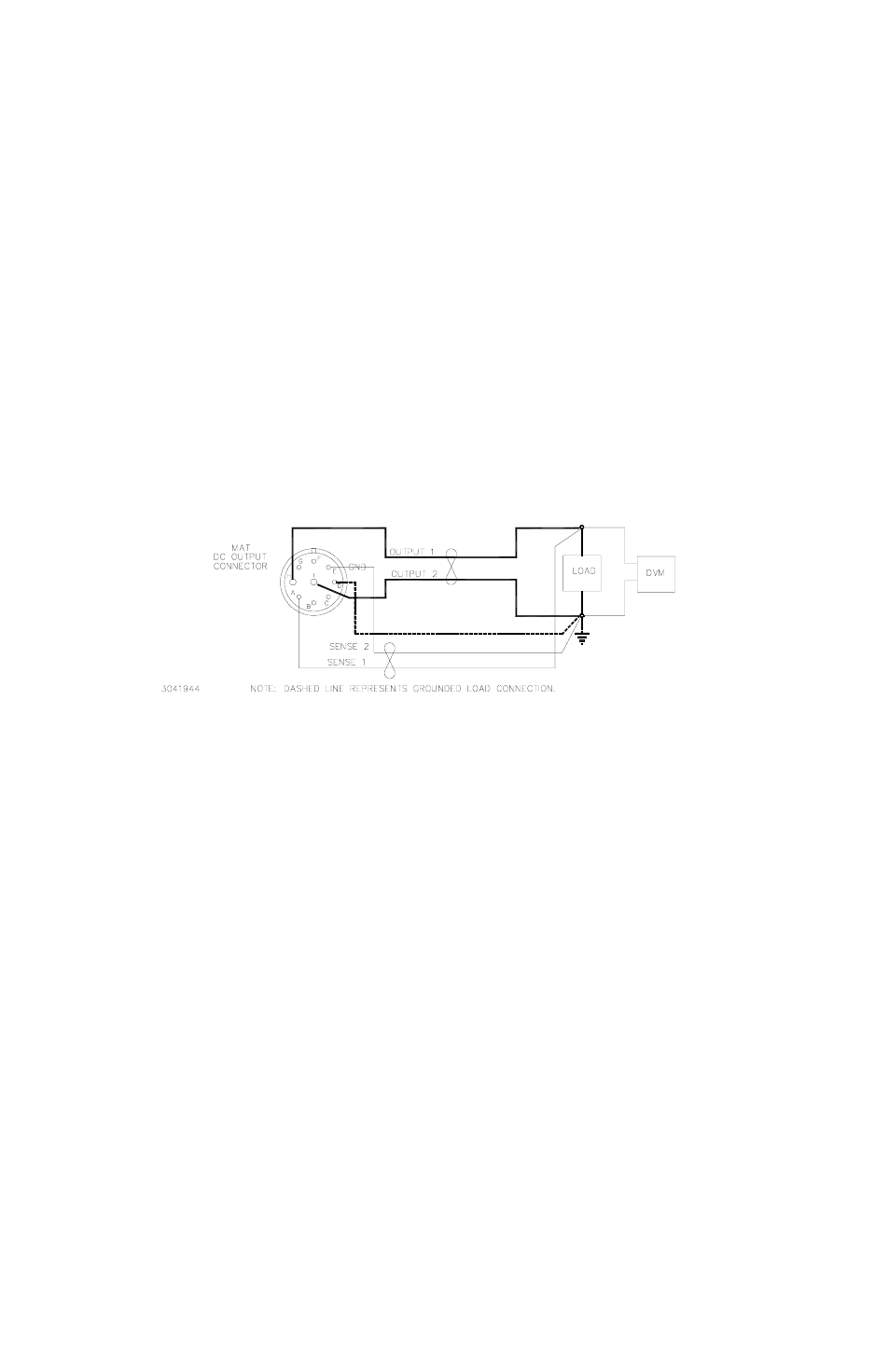
2.7.5
LOAD CONNECTION WITH REMOTE ERROR SENSING
The MAT series of Power Modules can operate with sensing external to the Module. Sensing
should be with a twisted wire pair to reduce noise. The sensing wires must be connected as fol-
lows: Output terminal 1 to Sense Terminal 1 and Output Terminal 2 to Sense Terminal 2, each at
the load (see Figure 2-6). Refer to Table 2-6 and Figure 2-2 for DC Output connector pin func-
tions and locations.
When the MAT Power Module is connected for remote error sensing (in the voltage mode), a sit-
uation might occur where the output capacitor C14 must be supplemented to achieve optimum
performance. If oscillations are observed at the output terminals or at the load, the load should
be decoupled with another high quality capacitor of a value equal to or greater than C14.
FIGURE 2-6. LOAD CONNECTIONS, REMOTE SENSING
2.8
OPERATING CONFIGURATION
The complete operating configuration is defined by
• The Model Number (e.g. MAT 36-10)
• Jumper configuration of internal boards.
Table 2-4 lists the location of the internal jumpers and their function. This information is provided
for reference purposes only, to indicate the configuration options available. Do not attempt to