Retrotec DucTester 200 Series Residential Applications User Manual
Page 82
Page 82 of 91
©Retrotec Inc. 2015
10. Set the old assembly aside, and connect the new one
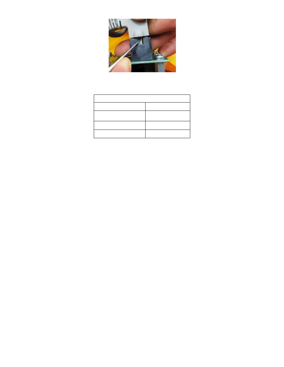
11. Connect the wires to the Power PCB assembly by attaching the flag connectors to the terminal posts
on the Power PCB as indicated. Be careful to not bend the PCB.
120v/240v
Green/Yellow
Labeled GND
Blue (Motor Wire)
J3-3 (Labeled WHT
115V)
Black
J3-7 (Labeled BLK)
Blue (Capacitor Wire)
J3-8 (Labeled BRN)
12. Ensure the Power PCB assembly sits on the fan shell cavity flush such that the wires and/or tubing are
not being pinched or crushed under the Power PCB assembly.
13. Re-attach the Power PCB assembly to the fan shell with the previously removed screws.